Table 3-16. Reference links to related information (continued)
Topic Related module Reference
Transfer Flash memory
controller
Flash memory controller
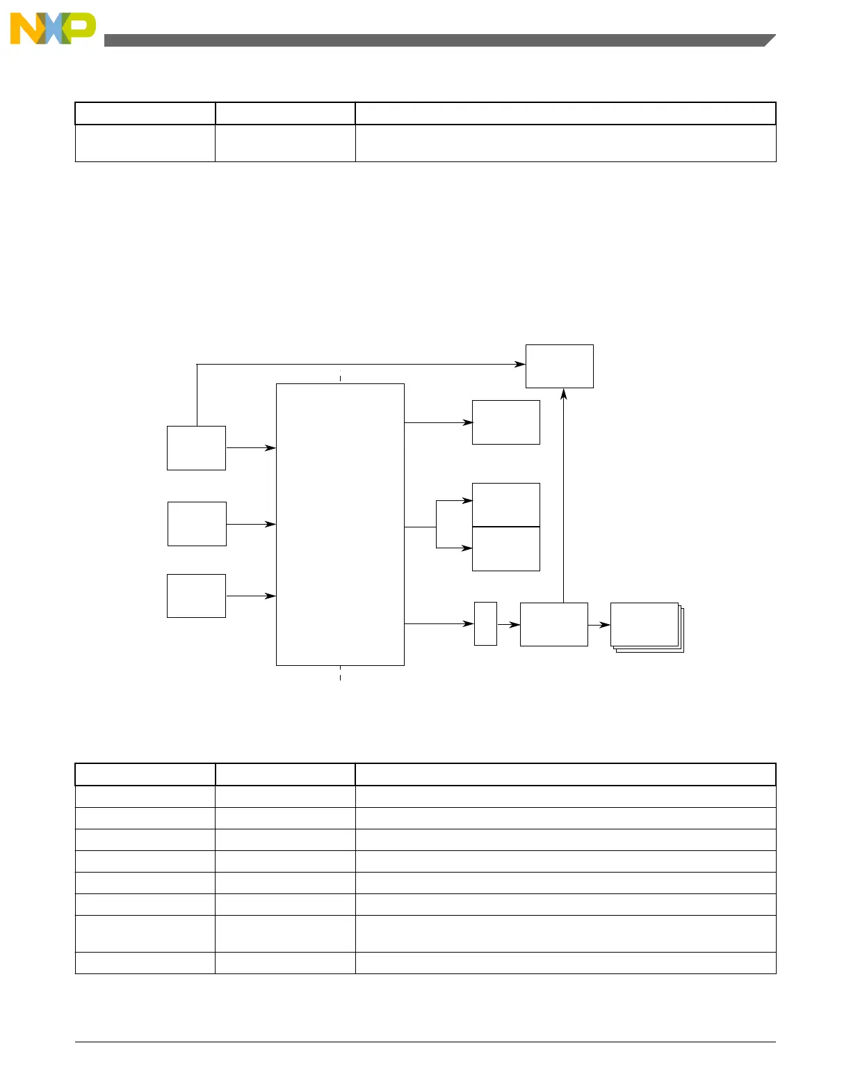
3.4.6 Crossbar-Light Switch Configuration
This section summarizes how the module has been configured in the chip. For a
comprehensive description of the module itself, see the module’s dedicated chapter.
Crossbar Switch
Slave Modules
Master Modules
M2
M0
S0
S2
ARM core
unified bus
DMA
Flash
controller
S1
SRAML
BME
Peripheral
bridge 0
GPIO
controller
SRAMU
Peripherals
USB
M3
Figure 3-9. Crossbar-Light switch integration
Table 3-17. Reference links to related information
Topic Related module Reference
Full description Crossbar switch Crossbar Switch
System memory map System memory map
Clocking Clock Distribution
Crossbar switch master ARM Cortex-M0+ core ARM Cortex-M0+ core
Crossbar switch master DMA controller DMA controller
Crossbar switch master USB FS/LS USB FS/LS
Crossbar switch slave Flash memory
controller
Flash memory controller
Crossbar switch slave SRAM controller SRAM configuration
Table continues on the next page...
Chapter 3 Chip Configuration
KL25 Sub-Family Reference Manual, Rev. 3, September 2012
Freescale Semiconductor, Inc. 61

 Loading...


