AXBS
CM0+ Core Platform
s1
s2
m0
s0
FMC
LD/ST
Dbg
NVIC
Fetch
Cortex-M0+ Core
MTB Port
AHB Bus
m2
AGU
MUL
RAM
Array
32
Dec Rn
SHFT
ALU
DMA_4ch
NVM
Array
PRAM
32
RGPIO
PBRIDGE
BME
32
IO Port
Slave
Peripherals
Alt-Master
m3
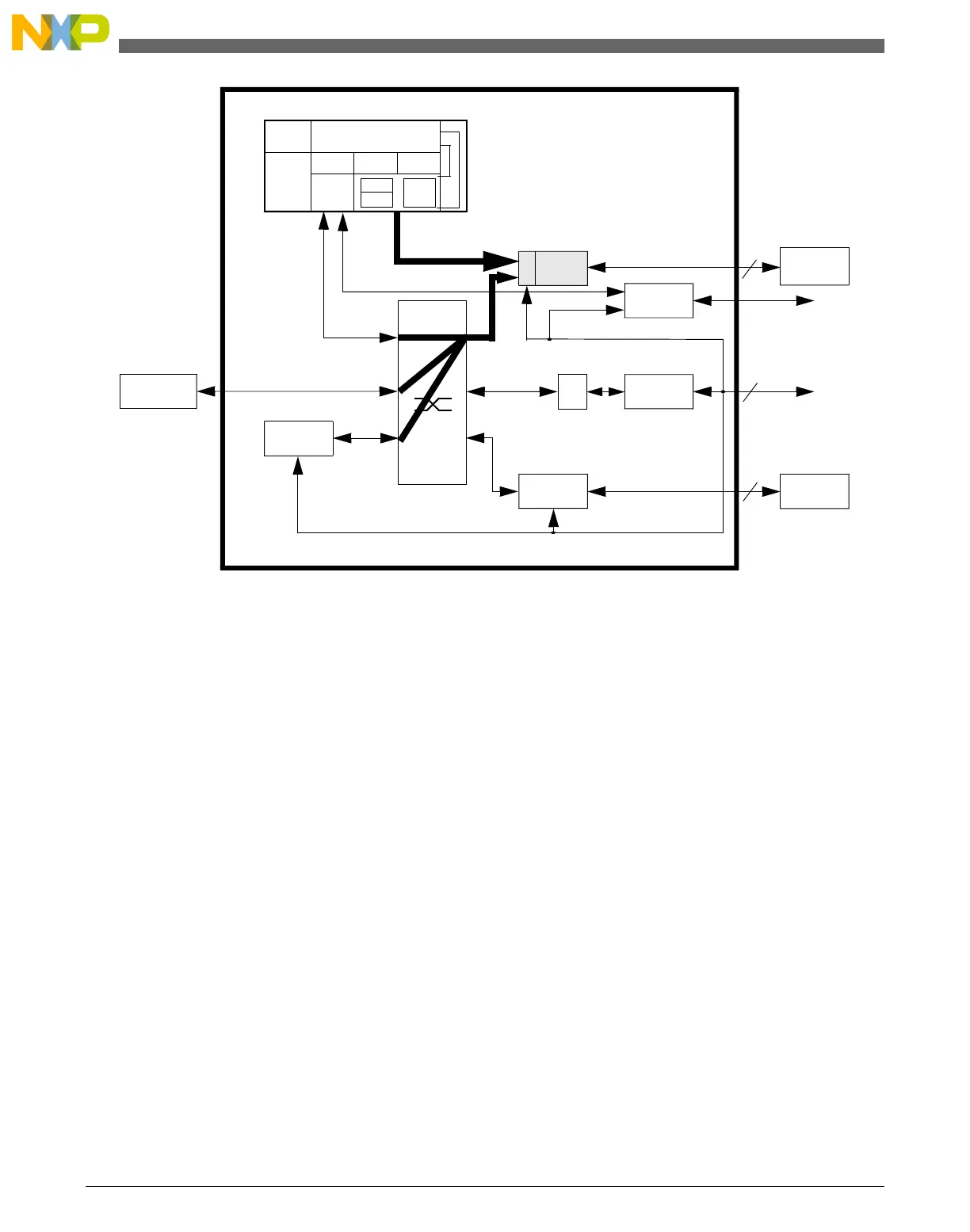
Figure 19-1. Generic Cortex-M0+ core platform block diagram
As shown in the block diagram, the platform RAM (PRAM) controller connects to two
input buses:
• the crossbar slave port for system bus accesses
• a "private execution MTB port" from the core
The logical paths from the crossbar master input ports to the PRAM controller are
highlighted along with the private execution trace port from the processor core. The
private MTB port signals the instruction address information needed for the 64-bit
program trace packets written into the system RAM. The PRAM controller output
interfaces to the attached RAM array. In this document, the PRAM controller is the
MTB_RAM controller.
The following information is taken from the ARM CoreSight Micro Trace Buffer
documentation.
"The execution trace packet consists of a pair of 32-bit words that the MTB generates
when it detects the processor PC value changes non-sequentially. A non-sequential PC
change can occur during branch instructions or during exception entry.
The processor can cause a trace packet to be generated for any instruction.
Introduction
KL25 Sub-Family Reference Manual, Rev. 3, September 2012
300 Freescale Semiconductor, Inc.

 Loading...


