-SCS Parameter Analyzer Reference Manual Appendix A: Using switch
4200A-901-01 Rev. C / February 2017 A-13
Row-column or instrument card settings
You select the scheme for interconnections between the instruments, the switch-matrix rows and
columns, and the test system (prober or test fixture). You can select:
• Row-Column: Connect instruments to rows and prober or test fixture to columns.
• Instrument Card: Both instruments and prober or test fixture are connected to columns. Matrix
rows are not used.
The row-column setting is the simplest connection scheme. In this scheme, instruments are
connected to the switch-matrix rows. The prober/test fixture pins or the device under test (DUT) are
connected to the switch-matrix columns (see Switch matrix control (on page A-16) and
4200A-SCS
signal paths (on page A-17)).
When you set up a matrix, you also select the sense. You can select:
• Local sense: 2-wire conections. Connections are only to instrument FORCE terminals.
• Remote sense: 4-wire connections. Connections are to both instrument FORCE and SENSE
terminals.
For more information regarding local and remote sense, refer to Remote sensing (on page 3-29
).
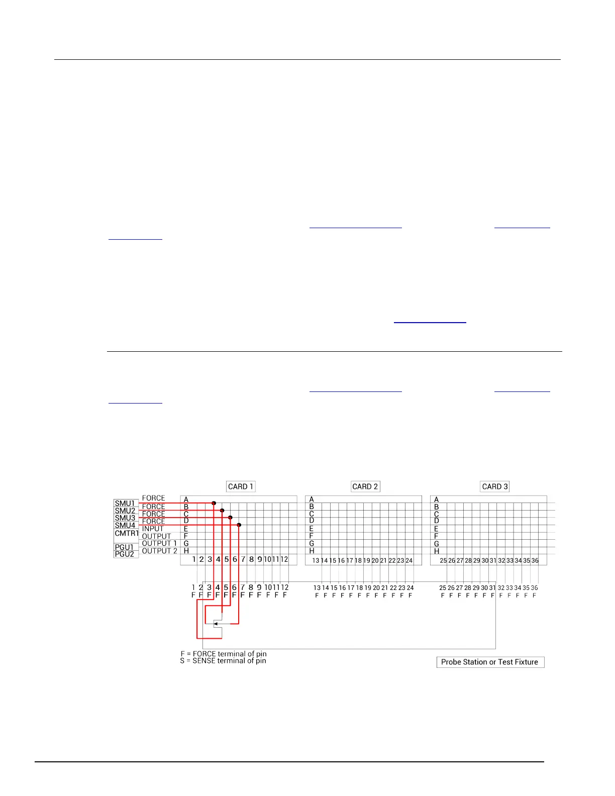
Row-column scheme
The row-column setting is the simplest connection scheme. In this scheme, instruments are
connected to the switch-matrix rows. The prober/test fixture pins or the device under test (DUT) are
connected to the switch-matrix columns (see Switch matrix control (on page A-16) and
4200A-SCS
signal paths (on page A-17)).
Instrument signals can route to prober/test-fixture pins through only one matrix card, as shown in the
following figure. However, the Row-Column scheme limits the number of external instruments. If the
instrumentation requirements exceed eight paths (rows), you must use the instrument card
configuration.
Figure 529: Row-Column, Local Sense Connection Scheme example
 Loading...


