-SCS Parameter Analyzer Reference Manual Section 5: Pulse measure and pulse generator units
4200A-901-01 Rev. C / February 2017 5-3
Use the RPM connectors on the 4225-PMU to connect it to the 4225-RPM (on page 5-6).
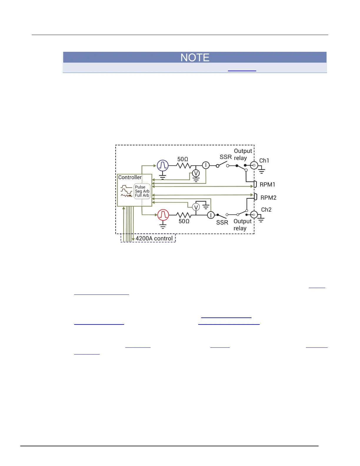
PMU block diagram
The next figure shows the block diagram of the PMU. Each channel has two dedicated A/D
converters to simultaneously measure current and voltage. The PMU controller controls the two
output channels and any RPMs connected to it. The solid-state relays (SSRs) are high-speed and are
used to test flash memory. The mechanical output relays are low-leakage. The block diagram for the
PGU is similar, except it does not have measure capability and does not have the RPM connectors.
Figure 143: 4225-PMU block diagram
Pulse modes
The PGU and PMU support the following pulse modes:
• Standard pulse mode: For this two-level pulse mode, the user defines a high and low level for the
pulse output. The test modes for standard pulse are pulse I-V and waveform capture. See
Pulse
parameter definitions (on page 5-40) for the standard (two-level) pulse mode.
• Segment Arb
®
waveform: For this multi-level pulse mode, the user defines a pulse waveform that
consists of three or more line segments. Segment Arb pulse mode for the PGU and PMU
includes sequencing and sequence looping (see seg_arb_sequence (on page 13-125
) and
seg_arb_waveform (on page 13-128). Also see Segment Arb waveform (on page 5-56) for details
on parameters.
• Full-arb pulse mode: For this multi-level pulse mode, the waveform consists of a number of user-
defined points (see arb_array (on page 13-131) and arb_file (on page 13-132)). Also see
Full Arb
waveform (on page 13-131) for details on parameters.
KPulse supports all of these pulse modes.
 Loading...


