G: Using a Cascade Microtech PA200 Prober Model 4200A-SCS Parameter Analyzer
G-2 4200A-901-01 Rev. C / February 2017
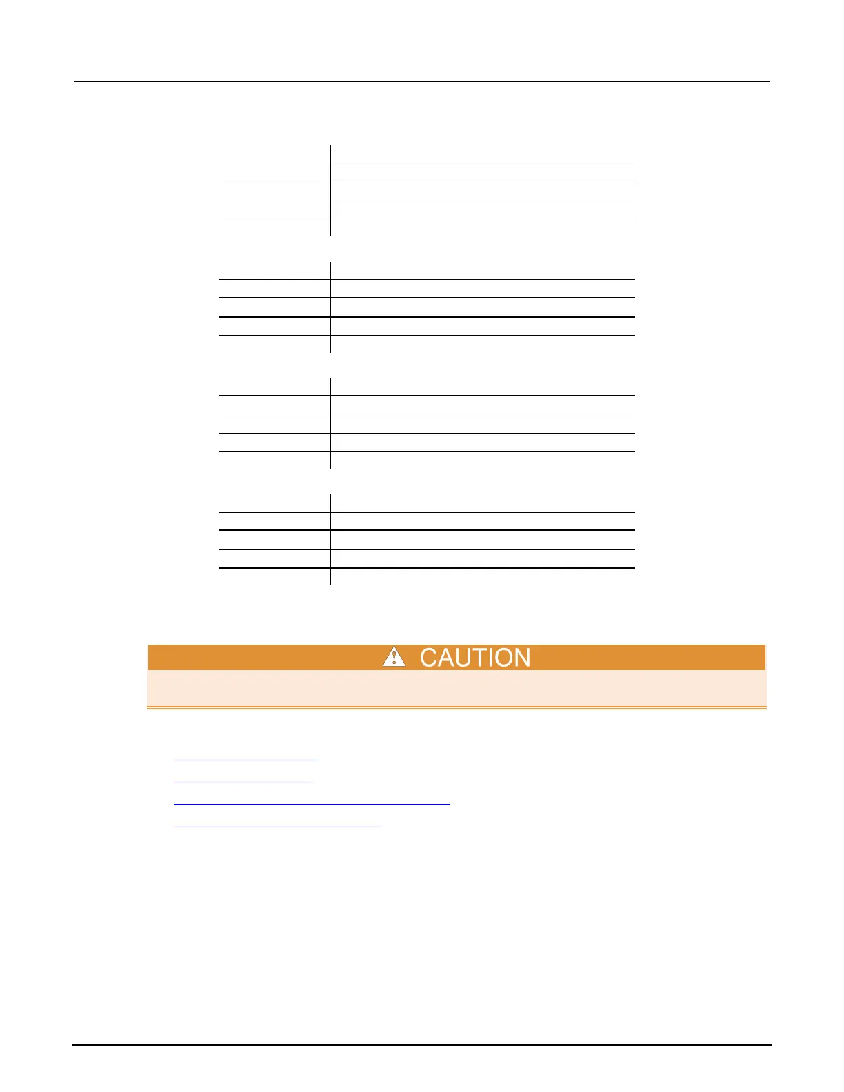
PBRS232 Interface for ProberBench NT
Copyright:
Karl Suss 1998 - All Rights Reserved
3.000000 ProberBench Kernel Version 3.10 12-7-98
2.400000 ProberBench Control Box 2.4
Navigator for ProberBench NT
©
Karl Suss 1998 - All Rights Reserved
3.000000 ProberBench Kernel Version 3.10 12-7-98
2.400000 ProberBench Control Box 2.4
TableView for ProberBench NT
Karl Suss 1998 - All Rights Reserved
Kernel: 3.000000 ProberBench Kernel Version 3.10 12-7-98
2.400000 ProberBench Control Box 2.4
Remote Communicator for ProberBench NT
Copyright:
©
Karl Suss 1998 - All Rights Reserved
3.000000 ProberBench Kernel Version 3.10 12-7-98
2.400000 ProberBench Control Box 2.4
Probe station configuration
Make sure that you are familiar with the Cascade MicroTech
®
PA200 Prober and its supporting
documentation before you attempt setup, configuration, or operation.
To set up and configure the PA200 prober for use with the 4200A-SCS, you will:
• Set up communications (on page G-6)
• Set up wafer geometry (on page G-10)
• Create a site definition and define a probe list (on page G-13)
• Load, align, and contact the wafer (on page G-14)
Set up communications
You need to set communications between the 4200A-SCS and the prober.
To make the connections:
1. Connect the ProberBench NT computer’s COM2 port to the 4200A-SCS COM1 port using a DB9
female to DB9 female cable (shielded null modem cable). See the following figure.