-SCS Parameter Analyzer Reference Manual Section 6:
4200A-901-01 Rev. C / February 2017 6-223
Open the Formulator
To open the Formulator:
1. In the project tree, select a test.
2. Select Configure.
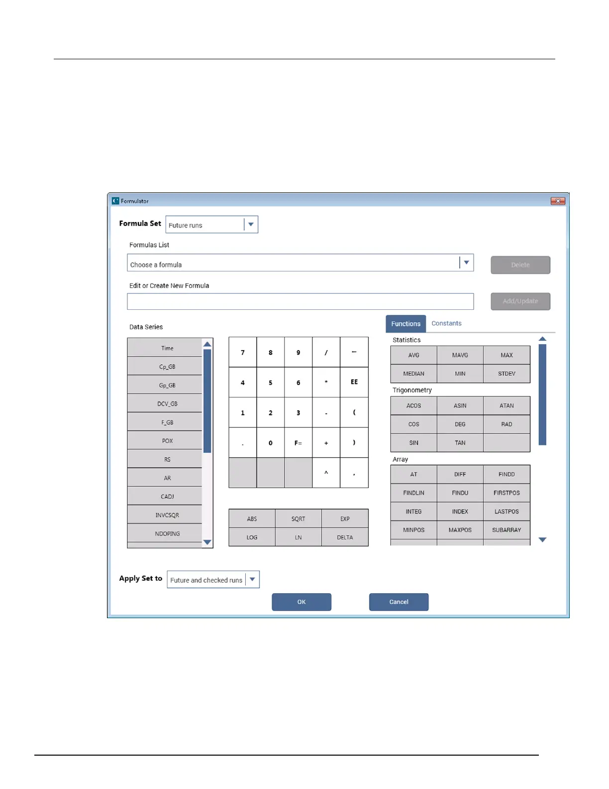
3. In the Test Settings pane, select Formulator. The Formulator dialog box opens, as shown below.
Figure 377: Formulator with no entries
 Loading...


