-SCS Parameter Analyzer Reference Manual Section 4: Multi-frequency capacitance-
4200A-901-01 Rev. C / February 2017 4-15
Generate load connection compensation data
Loads are reference resistors, typically 50 or 100 Ω or less, that must be resistive and constant over
the entire frequency range (1 kHz to 10 MHz). A load is connected to the output terminals using all
the cables, adaptors, probes and other hardware that will be in the test circuit.
To generate load correction data:
1. Make the connections to the 4210-CVU. See the Test connections for a switch matrix (on page 4-
7).
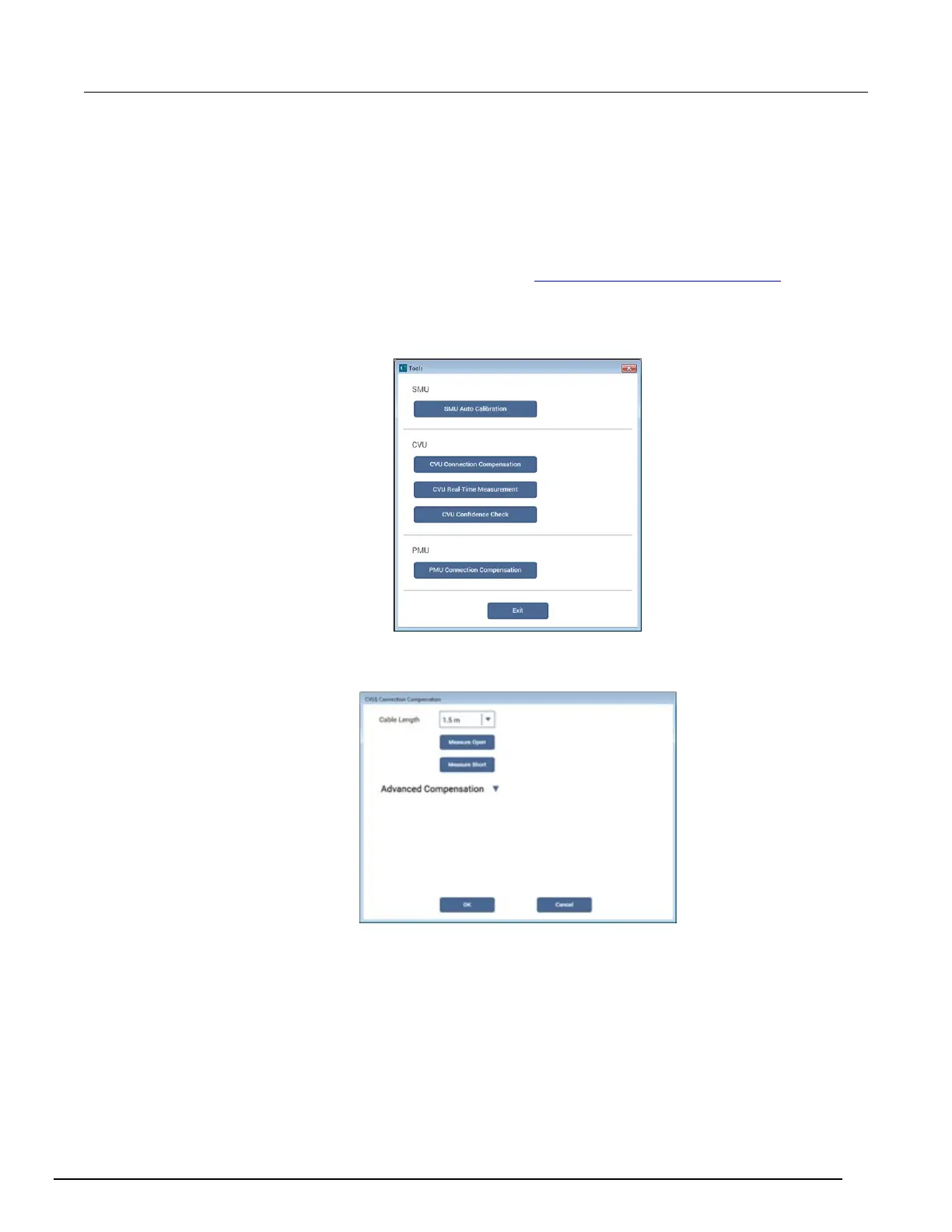
2. In Clarius, select Tools. The Clarius Tools dialog box opens.
Figure 92: Clarius Tools dialog box
3. Select CVU Connection Compensation.
Figure 93: CVU Connection Compensation dialog box
4. Select the cable length. You can select:
0 m: Use if measurements are made at the terminals of the 4210-CVU (no cables).
1.5 m: Use with the standard red SMA cables (part number CA-447A) that are supplied with
the 4210-CVU.
3 m: Use with the red SMA cables (part number CA-446) that are supplied with the
4200-CVU-Prober-Kit. You can also use this setting if you are using a switching matrix.
Custom: Cable length coefficients are measured by the user using the Measure Custom
Cable Length option under Advanced Compensation.
 Loading...


