5: Pulse measure and pulse generator units Model 4200A-SCS Parameter Analyzer
5-48 4200A-901-01 Rev. C / February 2017
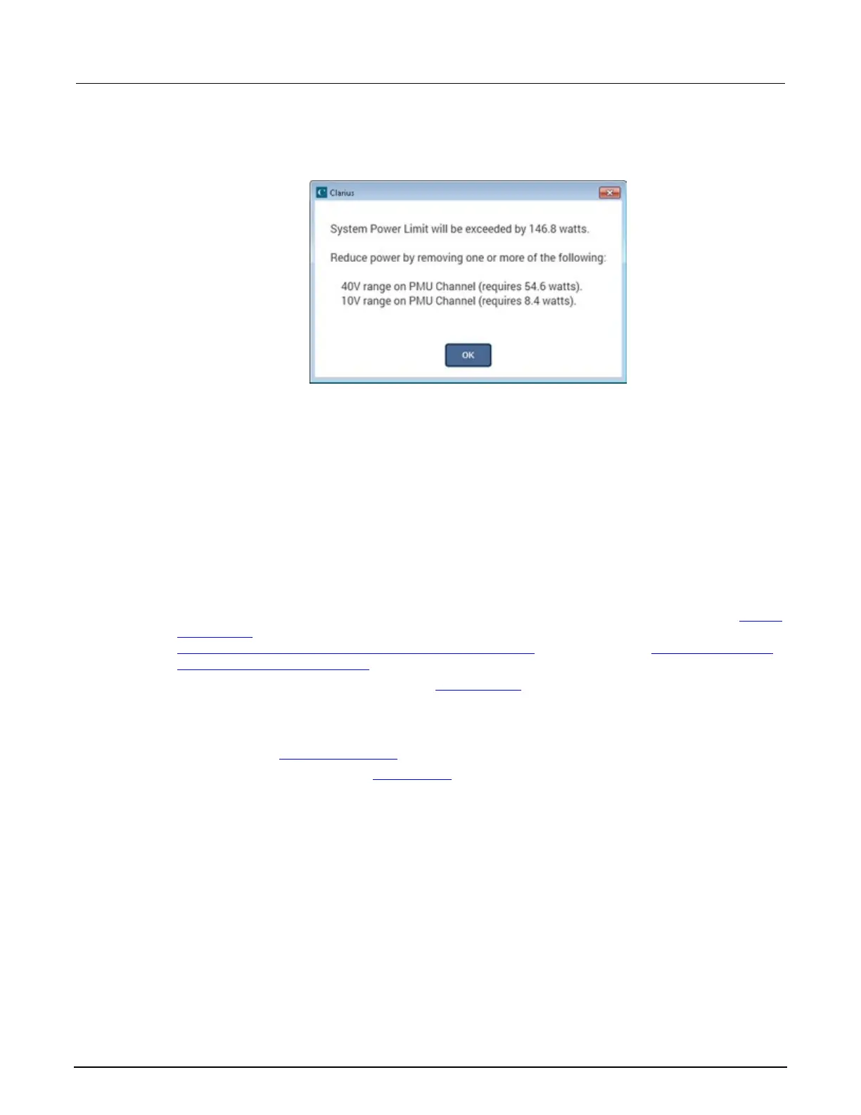
The power limit check is performed in both ITMs and UTMs. In ITMs, exceeding the power limit will
display a message similar to the one shown in the next figure when configuring PMU.
Figure 183: ITM maximum power exceeded message
For UTMs, the message appears in the Clarius Messages pane.
Basic troubleshooting procedure
If the test pulse I-V results do not meet expectations, use the following steps as a guide for
troubleshooting. Because the pulse I-V results extract the spot mean measurements from the top of
the pulse, good pulse I-V results require a reasonable pulse shape.
Step 1. Verify prober connections from the PMU or RPM to the DUT
1. Use cabling and connections optimized for high frequency (>150 MHz).
2. Connect the low side of the device under test (DUT) to the shield of the coaxial cable (see
Shield
connections (on page 5-11)), or connect the low side to another PMU or RPM channel (see
Connections to prober or test fixture bulkhead connectors (on page 5-16) or Pulse I-V (Average
pulses) measurement example (on page 6-99)).
3. Connect the shields (refer to the figure in Local sensing (on page 5-18) that shows four-terminal
local sense connections).
4. If you are not using the supplied cabling, minimize the loop area created by the shield and center
conductor. Do not use the GNDU connection for the return or ground path for any pulse I-V
signal. Refer to Shield connections (on page 5-11
).
5. Minimize the cable length. See Cable length (on page 5-11).
 Loading...


