-SCS Parameter Analyzer Reference Manual Section 6:
4200A-901-01 Rev. C / February 2017 6-47
Operation Mode (CVU)
The following topics describe the operation modes that are available when a CVU is selected as the
instrument.
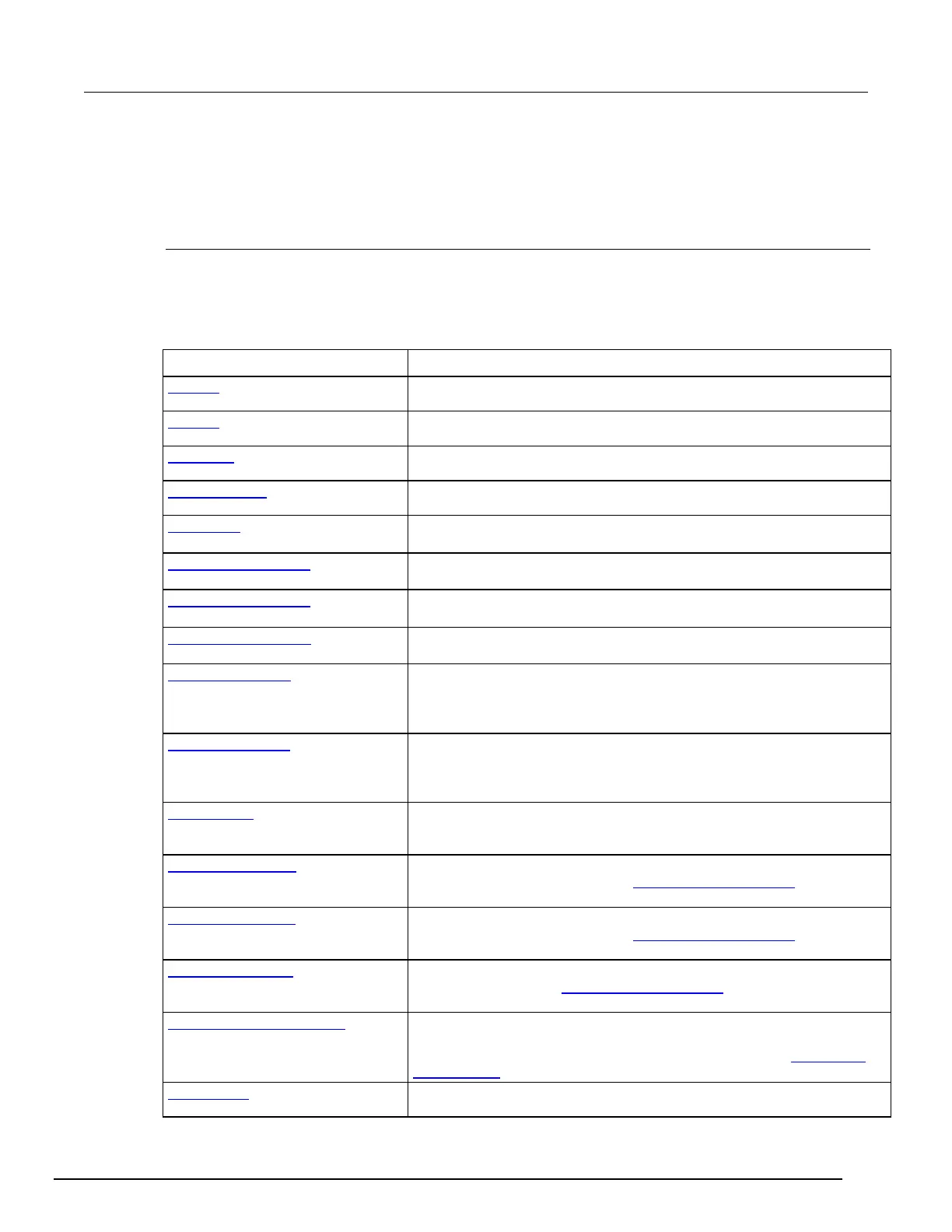
Voltage Bias operation mode - CVU
The Voltage Bias operation mode maintains a selected constant-voltage state at the terminal.
The parameters that are available for this mode are briefly described in the following table. Select the
links to access additional information. The parameters are listed in the order in which they appear in
the All Parameters pane.
Parameter Description
Type a presoak voltage of −30 V to +30 V.
The DC bias range accepts a value between −30 V to 30 V.
Frequency (on page 6-57) Select the frequency from the list of values.
AC Drive Signal (on page 6-57)
The AC drive signal accepts a value between 10 mV and 100 mV.
Parameters (on page 6-58)
Select the type of parameters. When using any of the tests supplied by
Keithley Instruments, leave the measurement option set to
.
Param1 Column Name (on page 6-
The name that is used for parameter 1 in the Analyze sheet.
Param2 Column Name (on page 6-
58)
The name that is used for parameter 2 in the Analyze sheet.
Report Test Conditions (on page 6-
58)
Select this option to display the DC bias and drive frequency values on the
Analyze sheet.
DCV Column Name (on page 6-59)
Available if you select Report Test Conditions. Determines the name of the
column that contains the DC bias information in the Analyze sheet where
this data is reported. You can change the name of the column by typing a
new value.
Freq Column Name (on page 6-59)
Available if you select Report Test Conditions. Determines the name of the
column that contains the frequency information in the Analyze sheet where
this data is reported. You can change the name of the column by typing a
Report Status (on page 6-59)
When this option is selected, Clarius records measurement status
information when the test executes. A column of the Analyze spreadsheet
displays this information. Hover over a cell to review the information.
Compensation Open (on page 6-59)
Use the CVU connection compensation value that was generated for open
connection compensation. Refer to Connection compensation (on page
4-
10) for information on generating and using compensation values.
Compensation Short (on page 6-59)
Use the CVU connection compensation value that was generated for short
connection compensation. Refer to Connection compensation (on page 4-
10) for information on generating and using compensation values.
Compensation Load (on page 6-60)
Use the CVU connection compensation value that was generated for load
compensation. Refer to Connection compensation (on page 4-10) for
information on generating and using compensation values.
Compensation Cable Length (on
page 6-60)
The cable length that was used to generate connection compensation data.
Make sure this cable length is the same as the Cable Length setting in the
Tools > CVU Connection Compensation dialog box. Refer to
Connection
compensation (on page 4-10) for additional information.
AC Source V (on page 6-60)
Selects the terminal to use to source AC drive voltage.
 Loading...


