-SCS Parameter Analyzer Reference Manual Section 3: Source-
4200A-901-01 Rev. C / February 2017 3-7
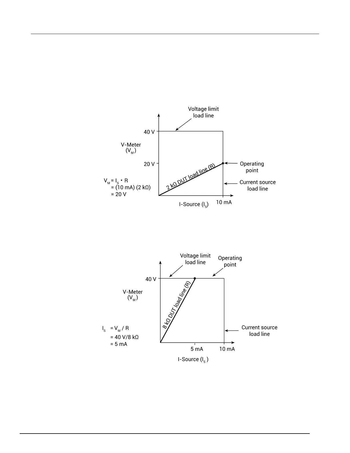
I-Source operation examples
The next figures show operation examples for resistive loads that are 2 kΩ and 8 kΩ, respectively.
For these examples, the SMU is programmed to source 10 mA and limit (compliance) 40 V. The SMU
is sourcing 10 mA to the 2 kΩ load, and subsequently measures 20 V. As shown, the load line for
2 kΩ intersects the 10 mA current source line at 20 V, which is below the programmed voltage limit.
Figure 35: Current source normal operation
The following figure shows what happens if the resistance of the load is increased to 8 kΩ. The DUT
load line for 8 kΩ intersects the 40 V voltage compliance limit line, placing the SMU in compliance. In
compliance, the SMU cannot source its programmed current (10 mA). For the 8 kΩ DUT, the SMU
only outputs 5 mA (at the 40 V limit).
Figure 36: Current source in compliance
Notice that as resistance increases, the slope of the DUT load line increases. As resistance
approaches infinity (open output), the SMU will source virtually 0 mA at 40 V. However, as resistance
decreases, the slope of the DUT load line decreases. At zero resistance (shorted output), the SMU
will source 10 mA at virtually 0 V.
Regardless of the load, voltage will never exceed the programmed compliance of 40 V.
 Loading...


