4: Multi-frequency capacitance-voltage unit Model 4200A-SCS Parameter Analyzer
4-72 4200A-901-01 Rev. C / February 2017
cf-10 pF test
This test performs a frequency sweep that measures capacitance at each frequency point and
generates a C versus F graph.
Analyze sheet
Test data is displayed in the Analyze sheet:
Measured parallel capacitance.
Status code for each measurement. Rows highlighted in blue indicate a
fault. For details, see CVU measurement status (on page 6-191).
NOTE: AB = Terminal A to Terminal B.
Interconnect Capacitance C-V Sweep test (cv-sweep)
Because the interconnect capacitance directly affects the speed and noise of an integrated circuit,
making accurate capacitance measurements is very important. These measurements are usually
measured between two metal pads on the wafer. The magnitude of capacitance is usually very small
(<1 pF).
This test uses a voltage sweep to measure capacitance at every step of the sweep and generates a
capacitance versus voltage graph. It also calculates noise.
This test module makes a C-V sweep. The measurements are set to Quiet mode because the
measurements are very sensitive.
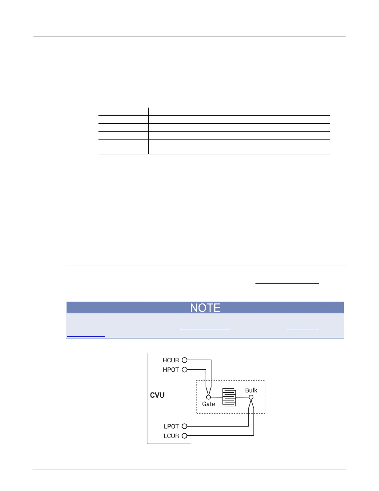
cv-sweep connections
The test configuration in the next figure shows the schematic representation of interconnect
capacitance on a wafer. For details on connections to the wafer, see 4210-CVU connections
(on page
4-5). Use only the supplied (red) 100 Ω SMA cables for connections to the 4210-CVU. Be sure that all
used SMA cables are the same length.
After making or changing connections, be sure to use the Confidence Check diagnostic tool and do
connection compensation tests. Refer to Confidence Check (on page 4-19) and Connection
compensation (on page 4-10) for details.
Figure 129: Basic configuration to test interconnect capacitance
 Loading...


