-SCS Parameter Analyzer Reference Manual Appendix A:
4200A-901-01 Rev. C / February 2017 A-15
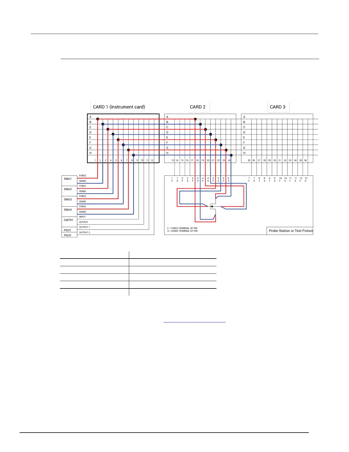
Instrument card scheme for remote sense
Use remote sense to eliminate the effects of measurement pathway resistance. The following figure
illustrates the use of remote sense in an instrument card configuration. Note that remote sense
requires twice as many measurement pathways. The FORCE pathways (in red) are the current-
carrying pathways, and the SENSE pathways (in blue) are the measurement pathways.
Figure 531: Instrument Card, Remote Sense Connection Scheme example
When remote sense is selected, rows and columns are paired together as follows:
Column 1 paired with Column 2
Column 3 paired with Column 4
Column 5 paired with Column 6
Column 7 paired with Column 8
Column 9 paired with Column 10
Column 11 paired with Column 12
When you specify a connection path in the connect action, the paired connection path is also
completed. For example, in the figure in 4200A-SCS signal paths (on page A-17
), the specified
connection paths would be:
• SMU1, 4 (connect SMU1 to Pin 4)
• GNDU, 3 (connect GNDU to Pin 3)
 Loading...


