-SCS Parameter Analyzer Reference Manual Appendix A:
4200A-901-01 Rev. C / February 2017 A-33
Details
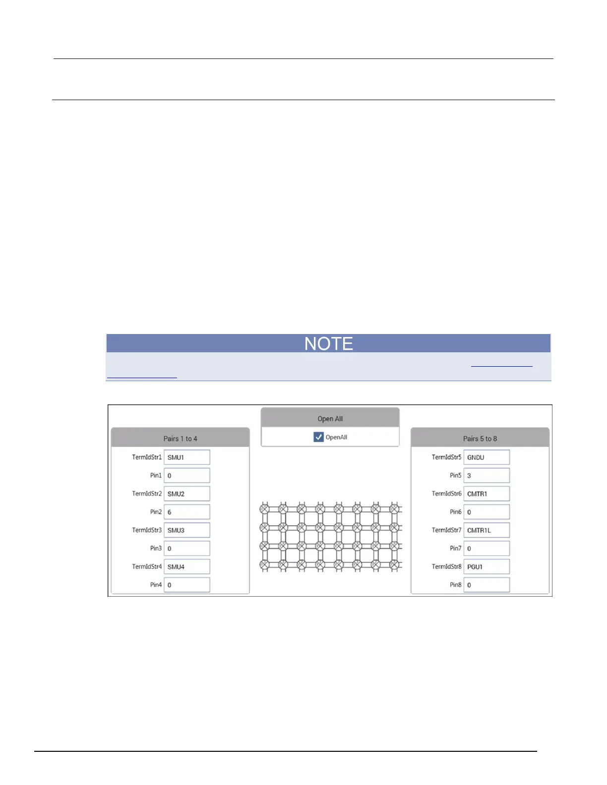
This user module allows you to control a switch matrix. The default input parameters are shown in the
following figure. Typically, OpenAll (line 1) is set to 1 to initially open all connections. If set to 0, the
present connections are not affected.
The rest of the input parameters are structured as terminal/pin pairs. Each terminal/pin pair specifies
the signal path through the matrix. For example, if the specified pin parameter for SMU1 is 4, then
SMU4 will connect to pin 4 of the test fixture or prober when the UTM is run. The pin parameter value
0 (or −1) indicates that no connection will be made.
Terminal ID: Terminal identification for the most common components used in the system
configuration are as follows:
• SMU1 to SMU4: These are the signal HI terminals for the four SMUs.
• GNDU: This is common terminal for the Ground Unit of the 4200A-SCS.
• CMTR1: This is used for a C-V Analyzer. For the 590, it is the OUTPUT terminal. For the
Keysight Model 4980A, it is the HCUR terminal.
• CMTR1L: This is also used for a C-V Analyzer. For the 590, it is the INPUT terminal. For the
Keysight Model 4980A, it is the LCUR terminal.
• PGU1: This is output HI for the Keysight Model 8110A Pulse Generator.
A test example demonstrates how this user module controls the switch matrix (see Switch matrix
control example (on page A-30)).
Figure 546: connectpins settings
 Loading...


