G: Using a Cascade Microtech PA200 Prober Model 4200A-SCS Parameter Analyzer
G-12 4200A-901-01 Rev. C / February 2017
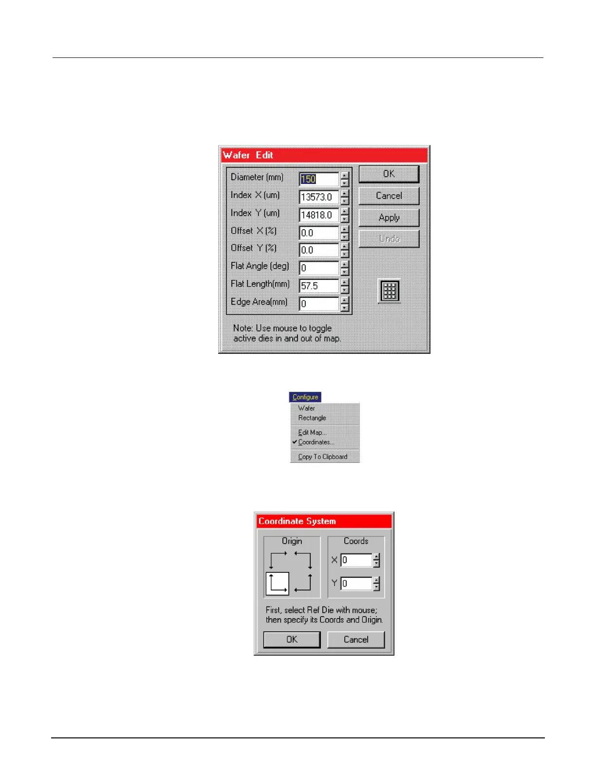
4. From the Configure menu, select Edit Map.
5. Enter the wafer geometry values and click Apply.
6. Click OK.
Figure 644: Wafer Edit dialog
7. From the Configure menu, select Coordinates.
Figure 645: Configure pull-down
8. From the Coordinate System dialog box, set Origin, as shown. You can set any initial X and Y
coordinates.
Figure 646: Coordinate System dialog box
9. Click OK.
 Loading...


