4: Multi-frequency capacitance-voltage unit Model 4200A-SCS Parameter Analyzer
4-68 4200A-901-01 Rev. C / February 2017
gni-w-wf test
This test is similar to the c-t test because it creates a Zerbst plot by biasing the device in
accumulation for a specified period. However, it calculates the generation rate (GN
I
) and the depletion
depth (WW
F
) for every measurement, and then generates a GN
I
versus WW
F
Zerbst plot.
This test creates a Zerbst plot by first biasing the device in accumulation for a specified period. At
time = 0, the polarity of the bias voltage is reversed to drive the device into deep depletion. While
holding this bias, the capacitance is measured as a function of time. As more minority carriers are
generated, the measured capacitance will rise. Eventually it will reach the minimum capacitance on
the standard C-V curve. From both the C-t and the C-V data, the generation rate (G/n
i
) is plotted as a
function of depletion depth (w-w
F
). You must manually input the values of C
OX
, C
MIN
, and N
AVG
taken
from the cv test into the Formulator in order to calculate the generation rate and depletion depth.
Note that a known value of N
AVG
can be input into the Formulator instead.
Once G/n
i
versus w-w
F
is plotted, a linear line fit is applied to the graph. The generation lifetime (τ
G
) is
the reciprocal of the slope of the linear fitted region of the graph. The surface generation velocity (s
G
)
is the y-axis (G/n
i
) intercept of the same linear section of the Zerbst plot.
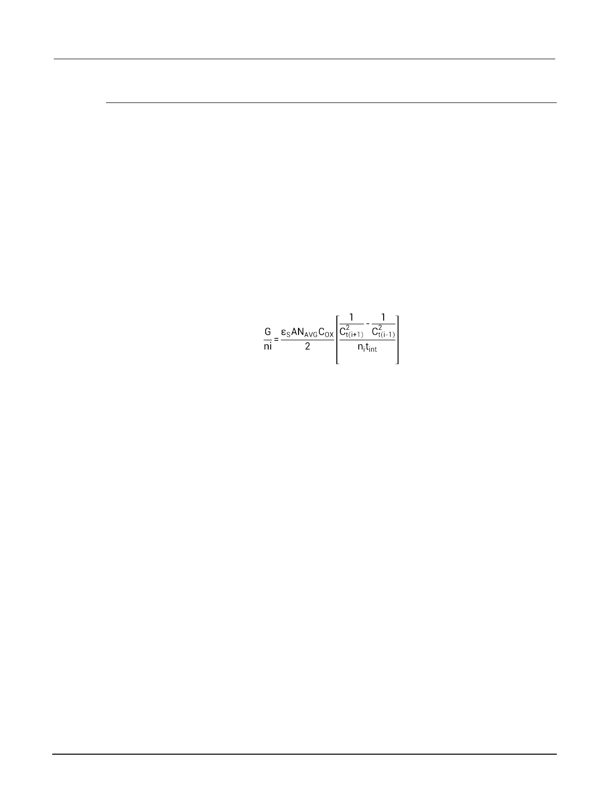
The generation rate is calculated as follows:
Where:
• G/n
i
= generation rate (s
-1
)
• ε
S
= permittivity of the substrate material (F/cm)
• A = gate area (cm
2
)
• N
AVG
= average doping concentration (cm
-3
)*
• C
OX
= oxide capacitance (F)
• C
2
t(i+1)
= (i+1) value of measured C-t capacitance (F)
• C
2
t(i-1)
= (i-1) value of measured C-t capacitance (F)
• n
i
= intrinsic carrier concentration (cm
-3
)
• t
int
= time interval between C-t measurements (s)
*N
AVG
is calculated (with the result placed in the Analyze sheet) when the C-V test is run. The value
for this parameter must be input into the Formulator for the gni-w-wf test. You can input a known
value of N
AVG
into the Formulator instead.
 Loading...


