-SCS Parameter Analyzer Reference Manual Section 4: Multi-frequency capacitance-
4200A-901-01 Rev. C / February 2017 4-81
Notice from the high frequency curve that when the device is in the inversion region, the capacitance
is high, unlike the MOS capacitor, which has low capacitance in inversion. This is because the
MOSFET has a source and drain, which enables inversion charge to flow, unlike the MOS capacitor,
which relies on generation and recombination in the bulk region.
The oxide capacitance (C
OX
) is usually set to the maximum capacitance in accumulation, and is
calculated by the C
OX
formula in the Formulator.
Oxide thickness is calculated by the T
OX
formula in the Formulator.
The mosfet-dopingprofile test performs a C-V sweep on the two-terminal MOSFET. It
generates a doping concentration versus depletion depth graph. The doping concentration (N) is
calculated and plotted as a function of depletion depth. Depletion depth is calculated by the DEPTHM
formula in the Formulator.
Doping density is calculated from the measured capacitance and the voltage. It is calculated by the
NDOPING formula in the Formulator.
mosfet connections
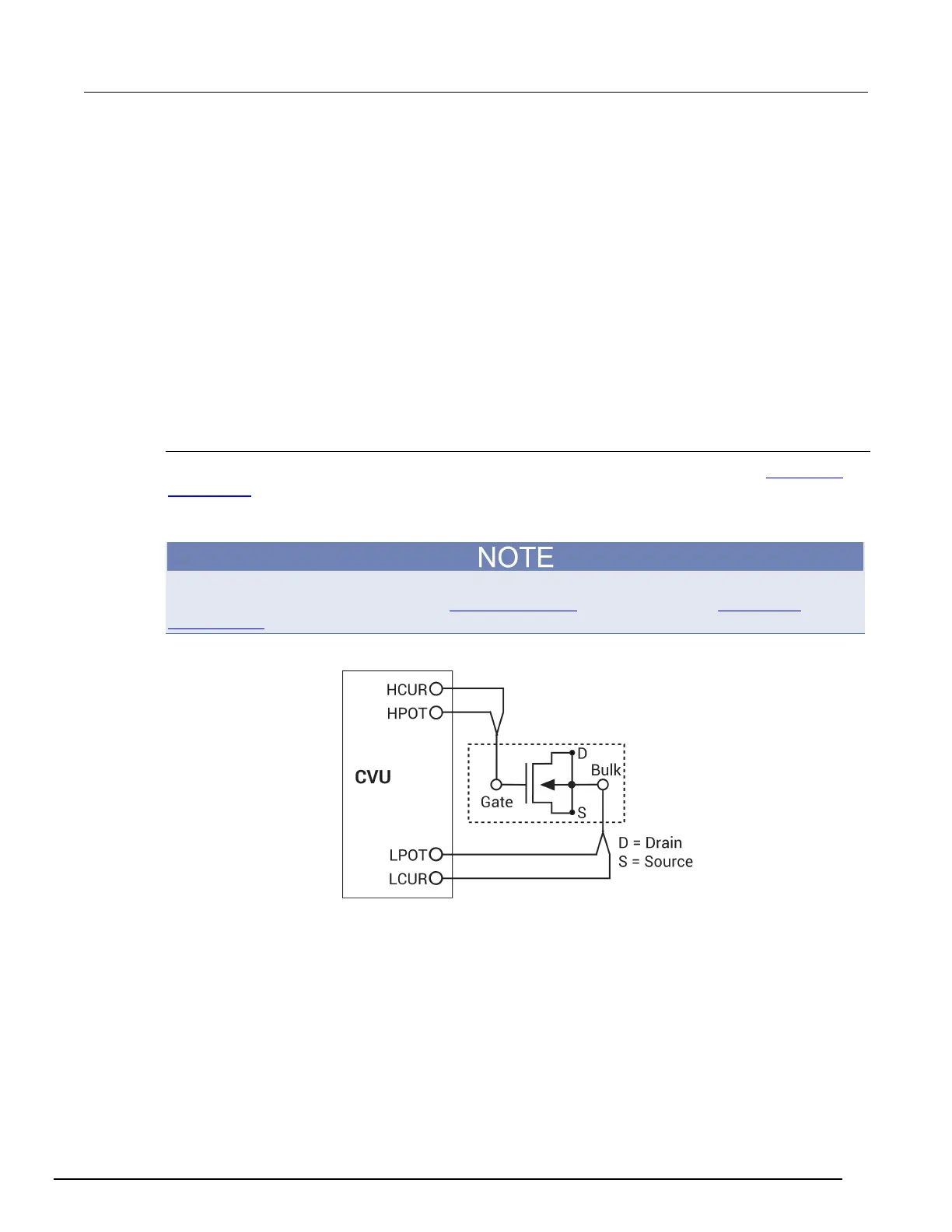
The next figure shows the basic test configuration for MOSFET testing (for details, see 4210-CVU
connections (on page 4-5)). As shown, 2-wire sense connections are used with the source, drain, and
bulk terminals tied together. Use only the supplied CA-446A or CA-447A red 100 Ω SMA cables for
connections to the 4210-CVU. Be sure that all used SMA cables are the same length.
After making or changing connections, be sure to use the Confidence Check diagnostic tool and do
connection compensation tests. Refer to Confidence Check (on page 4-19) and Connection
compensation (on page 4-10) for details.
Figure 135: Two-terminal C-V test configuration for a MOSFET
 Loading...


