-SCS Parameter Analyzer Reference Manual Section 5: Pulse measure and pulse generator units
4200A-901-01 Rev. C / February 2017 5-7
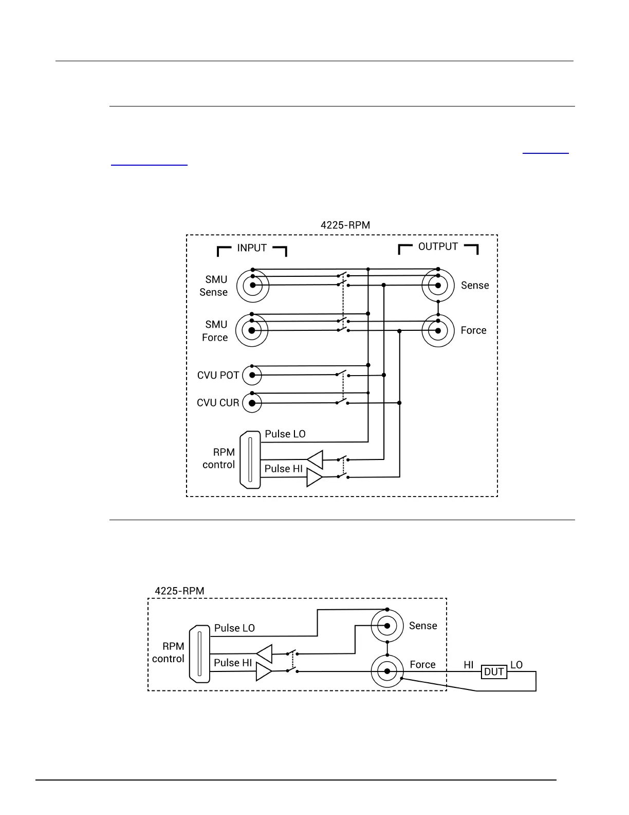
RPM wiring diagram
The internal wiring diagram of the RPM is shown in the next figure.
Signals from the 4200A-SCS instrument cards are routed through the RPM to the output Force and
Sense connectors. Switching is used to control which card is connected to the output. See
Using the
RPM as a switch (on page 5-8) for more information on switching.
The LEDs on the top panel (see the previous figure) indicate which card is connected to the output.
By default, the RPM (pulse mode) is connected to the output unless a SMU or CVU is switched in.
Figure 145: Wiring diagram of the RPM
RPM diagrams for local and remote sensing
The next figure shows the diagram for local sensing. The center conductor of the Force triaxial
connector is connected to the high side of the device under test (DUT) while the outer shield is
connected to DUT LO. The Sense connector is not used.
Figure 146: RPM wiring diagram for local sensing
 Loading...


