Chapter 10
234 MIPS R4000 Microprocessor User's Manual
10.4 Connecting Clocks to a Phase-Locked System
When the processor is used in a phase-locked system, the external agent
must phase lock its operation to a common MasterClock. In such a system,
the delivery of data and data sampling have common characteristics, even
if the components have different delay values. For example, transmission
time (the amount of time a signal takes to move from one component to
another along a trace on the board) between any two components A and B
of a phase-locked system can be calculated from the following equation:
Transmission Time = (SClock period) – (t
DO
for A) – (t
DS
for B) –
(Clock Jitter for A Max) – (Clock Jitter for B Max)
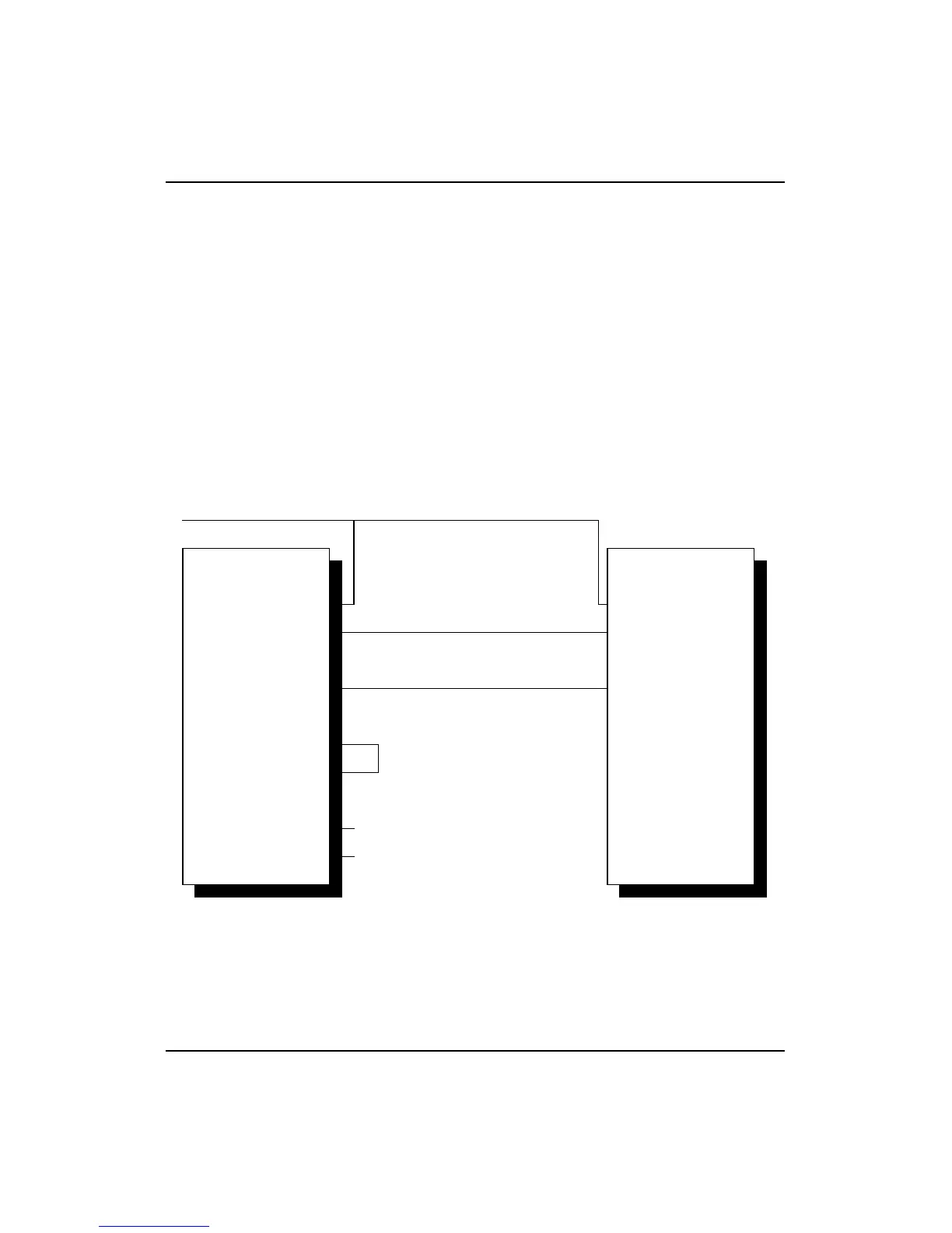
Figure 10-5 shows a block-level diagram of a phase-locked system using
the R4000 processor.
Figure 10-5 R4000 Processor Phase-Locked System
MasterClock
R4000
TClock
RClock
SysAD
SysCmd
MasterClock
SyncOut
SyncIn
MasterClock
External Agent
SysCmd
SysAD