MIPS R4000 Microprocessor User's Manual D-3
Output Buffer Control Mechanism
The designer determines the trace characteristics by:
• measuring the longest path from an R4000 output driver to a
receiving device, L
• calculating the maximum capacitive loading on any signal pin,
C
• connecting an incident-wave trace of length L with a capacitive
loading of C between the IO_In and IO_Out pins of the R4000
• connecting a reflected wave trace of length L/2 to the IO_In
pin of the R4000.
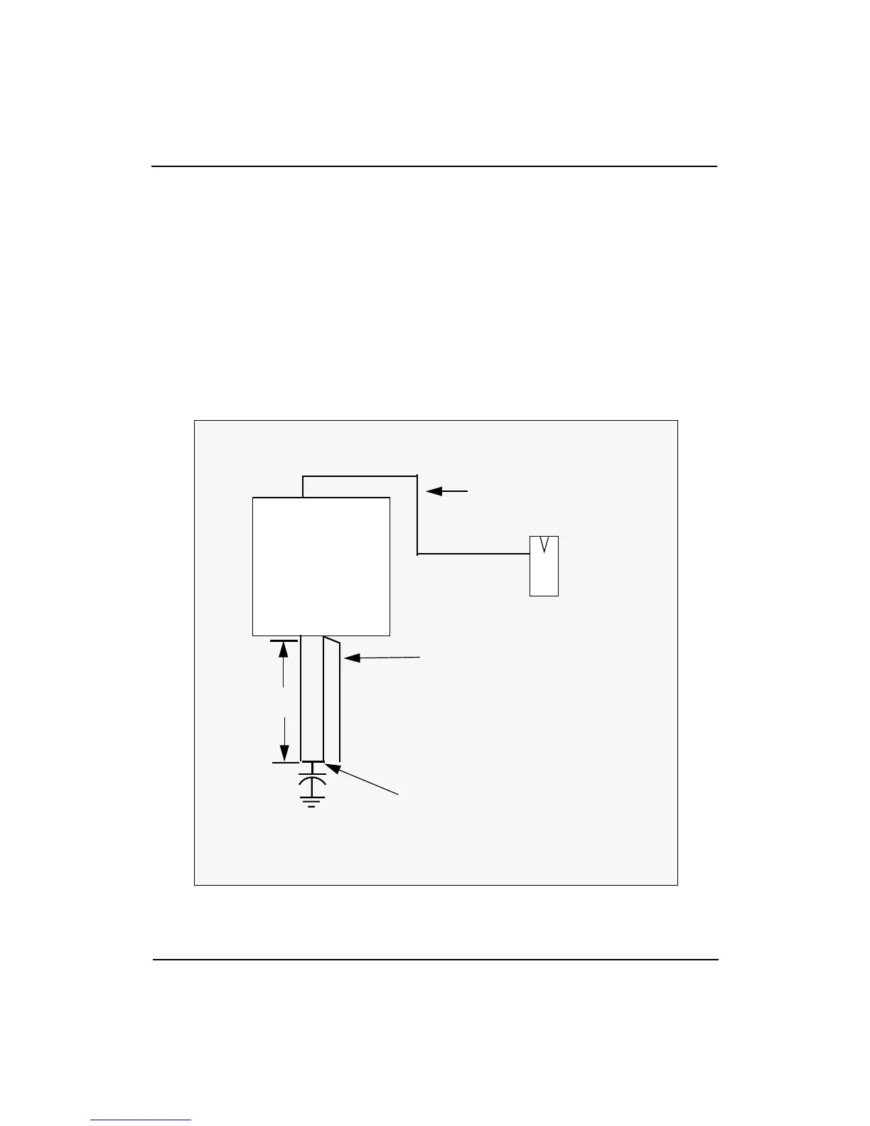
An R4000 with appropriate traces connected to the IO_In and IO_Out
pins is illustrated in Figure D-1.
Figure D-1 O_In/IO_Out Board Trace
CPU Board
R4000
“Reflected wave” trace
“Incident Wave” Trace
C
Load
= C
Length = L/2
IO_InIO_Out
a
b
c
L = a + b + c + d
C = Total Capacitance Loading
d
The longest trace from an
R4000 output driver to a
receiving device
of the worst case trace