MIPS R4000 Microprocessor User's Manual 81
Memory Management
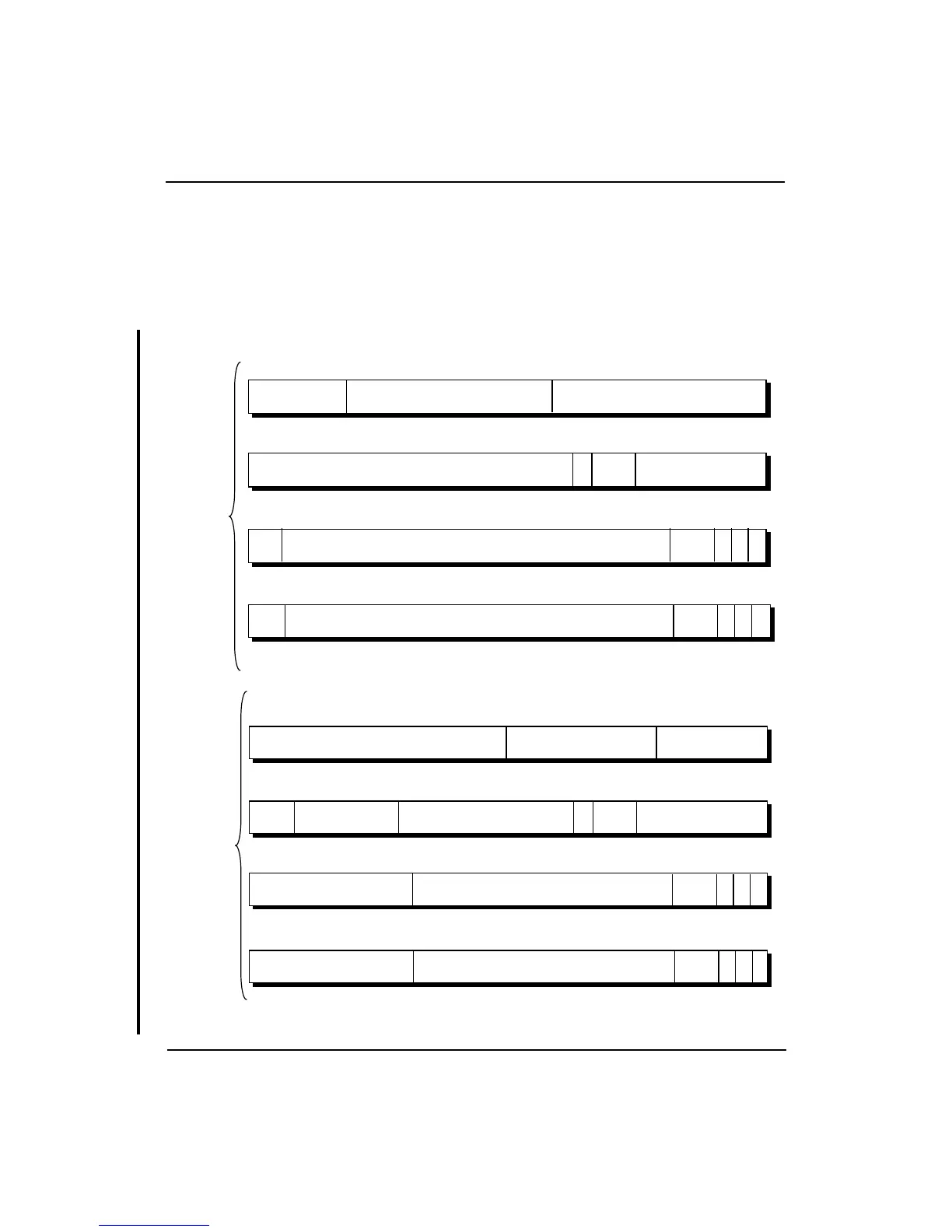
Format of a TLB Entry
Figure 4-8 shows the TLB entry formats for both 32- and 64-bit modes.
Each field of an entry has a corresponding field in the EntryHi, EntryLo0,
EntryLo1, or PageMask registers, as shown in Figures 4-9 and 4-10; for
example the Mask field of the TLB entry is also held in the PageMask
register.
Figure 4-8 Format of a TLB Entry
12
127
13
96
MASK 0
95
VPN2 G
19
64
14 8
ASID
7677
24
63 32
PFN
31 0
7
0
121 120 109 108
75
72 71
62 61
2
CVD
311
3334353738
0
1
24
PFN
30 29
2
C
VD
311
12356
0
1
0
0
0
12
255
13
192
MASK
0
191
VPN2
G
27
128
14 8
ASID
140141
24
127 64
PFN
63 0
39
0
139136 135
94 93
C
VD
311
6566676970
0
1
24
PFN
30 29
34
C
VD
311
12356
0
1
0
0
32-bit Mode
64-bit Mode
34
0
167168
R
190 189
22
0
2
204205216217
128-bit TLB
entry in 32-
bit mode of
R4000
processor
256-bit TLB
entry in 64-
bit mode of
R4000
processor