MIPS R4000 Microprocessor User's Manual 391
JTAG Interface
14.2 Signal Summary
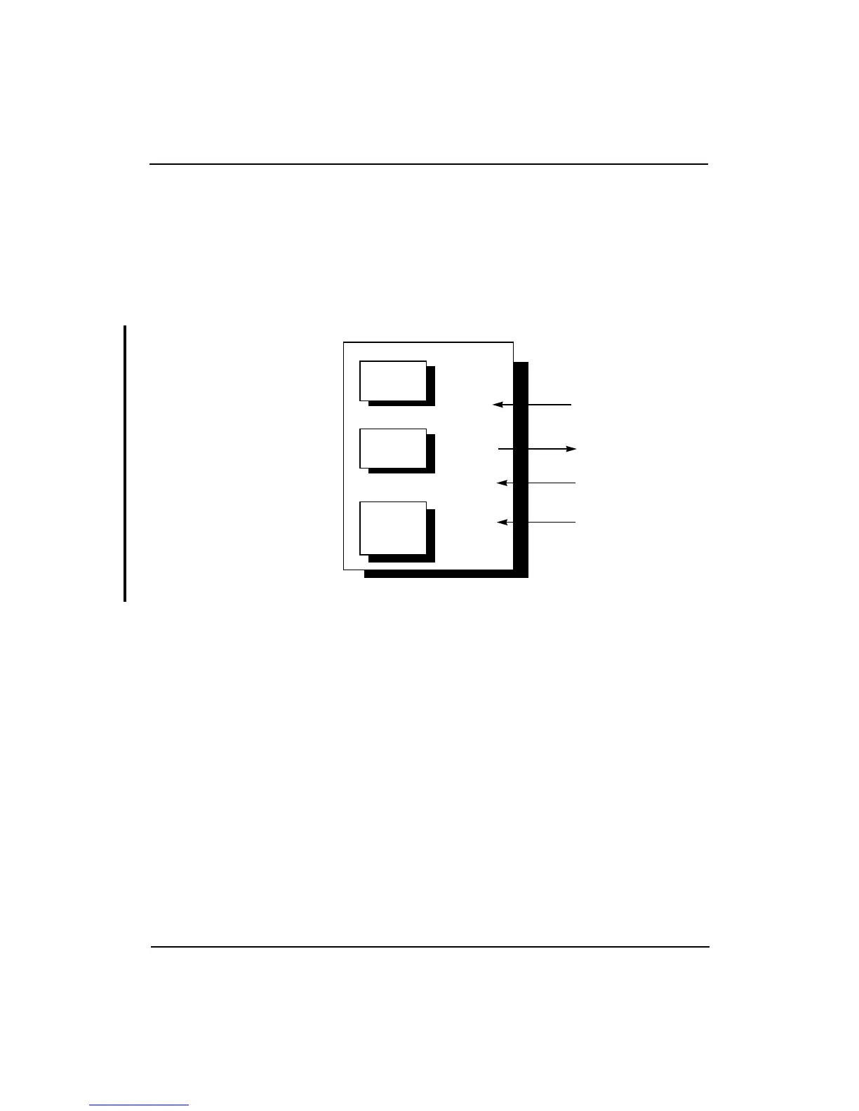
The JTAG interface signals are listed below and shown in Figure 14-2.
JTDI JTAG serial data in
JTDO JTAG serial data out
JTMS JTAG test mode select
JTCK JTAG serial clock input
Figure 14-2 JTAG Interface Signals and Registers
The JTAG boundary-scan mechanism (referred to in this chapter as JTAG
mechanism) allows testing of the connections between the processor, the
printed circuit board to which it is attached, and the other components on
the circuit board.
In addition, the JTAG mechanism provides rudimentary capability for
low-speed logical testing of the secondary cache RAM. The JTAG
mechanism does not provide any capability for testing the processor itself.
CPU
JTD0 pin
Context is
saved
Instruction
register
Context is
saved
Boundary-
scan
register
Context is
saved
Bypass
register
02
0
1
319
JTDI pin
JTMS pin
JTCK pin