Chapter 11
252 MIPS R4000 Microprocessor User's Manual
Organization of the Secondary Cache
Each secondary cache line has an associated 19-bit tag that contains bits
35:17 of the physical address, a 3-bit primary cache index, VA(14:12), and
a 3-bit cache line state. These 25 bits are protected by a 7-bit ECC code.
The secondary cache is accessible to the processor and to the system
interface; by setting the appropriate boot-mode bits, it can be configured
at chip reset as a joint cache, or as separate I- and D-caches.
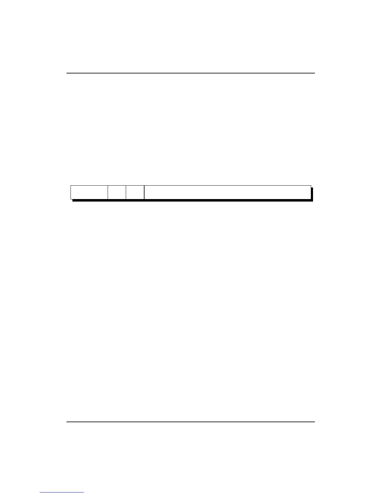
Figure 11-6 shows the format of the R4000 processor secondary-cache line.
The size of the secondary cache line is set in the SB field of the Config
register.
Figure 11-6 R4000 Secondary Cache Line Format
19
31 0
CS
7
ECC
24 1925 22 21
PIdx STag
33
ECC ECC for secondary tag
CS Secondary-cache state
0 = Invalid
1 = reserved
2 = reserved
3 = reserved
4 = Clean Exclusive
5 = Dirty Exclusive
6 = Shared
7 = Dirty Shared
PIdx Primary cache index (bits 14:12 of the virtual address)
STag Physical tag (bits 35:17 of the physical address)
18