MIPS R4000 Microprocessor User's Manual 203
R4000 Processor Signal Descriptions
8.2 Clock/Control Interface Signals
The Clock/Control interface signals make up the interface for clocking
and maintenance. Table 8-2 lists the Clock/Control interface signals.
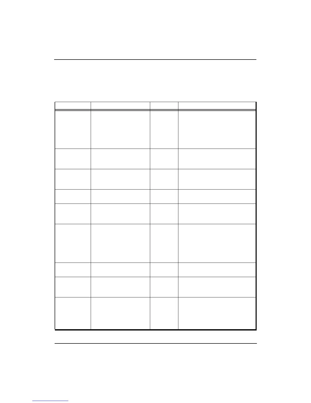
Table 8-2 Clock/Control Interface Signals
Name Definition Direction Description
IOOut I/O output Output
Output slew rate control
feedback loop output. Must be
connected to IOIn through a
delay loop that models the I/O
path from the processor to an
external agent.
IOIn I/O input Input
Output slew rate control
feedback loop input (see
IOOut).
MasterClock Master clock Input
Master clock input that
establishes the processor
operating frequency.
MasterOut Master clock out Output
Master clock output aligned
with MasterClock.
RClock(1:0) Receive clocks Output
Two identical receive clocks that
establish the System interface
frequency.
SyncOut
Synchronization
clock out
Output
Synchronization clock output.
Must be connected to SyncIn
through an interconnect that
models the interconnect
between MasterOut, TClock,
RClock, and the external agent.
SyncIn
Synchronization
clock in
Input Synchronization clock input.
TClock(1:0) Transmit clocks Output
Two identical transmit clocks
that establish the System
interface frequency.
Fault* Fault Output
The processor asserts Fault* to
indicate a mismatch output of
boundary comparators, and
indication of System interface
input parity or ECC errors.