MIPS R4000 Microprocessor User's Manual 355
System Interface
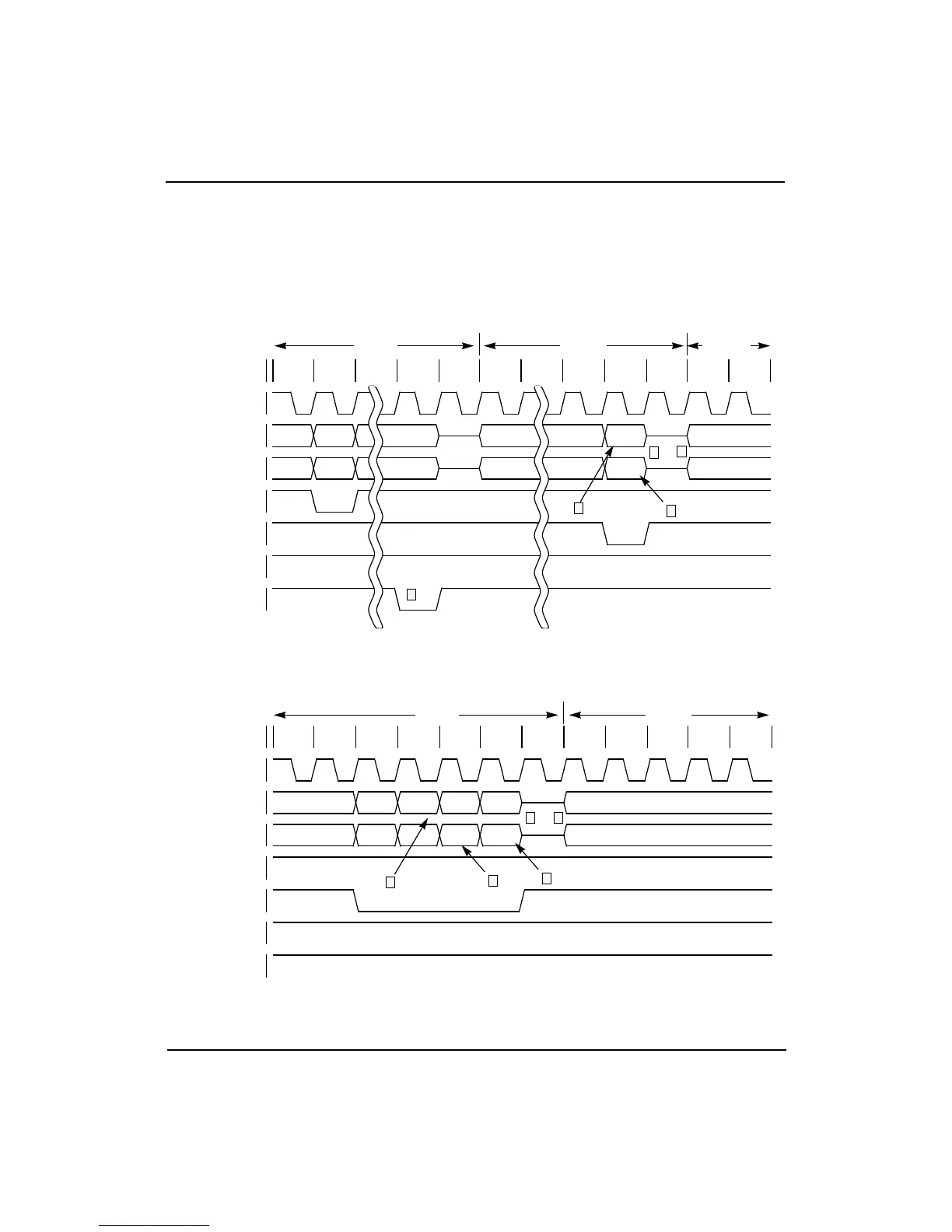
Figure 12-38 illustrates a processor word read request followed by a word
read response. Figure 12-39 illustrates a read response for a processor
block read with the System interface already in slave state.
NOTE: Timings for the SysADC and SysCmdP buses are the same as
those of the SysAD and SysCmd buses, respectively.
Figure 12-38 Processor Word Read Request, followed by a Word Read Response
Figure 12-39 Block Read Response, System Interface already in Slave State
SCycle
1 2 3 4 5 6 7 8 9 10 11 12
SClock
SysAD Bus
Addr Data0
SysCmd Bus
Read NEOD
ValidOut*
ValidIn*
ExtRqst*
Release*
6
1
2
3
4
Master Slave Master
SCycle
1 2 3 4 5 6 7 8 9 10 11 12
SClock
SysAD Bus
Data0 Data1 Data2 Data3
SysCmd Bus
CData CData CData CEOD
ValidOut*
ValidIn*
ExtRqst*
Release*
6
2
3
4
5
Slave Master