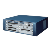
Figure 4-12 Two-cabinet system - connecting cable between BC and EC1
Three-cabinet system: connecting cable diagram (see Table 4-3)
Figure 4-13 Three-cabinet system - connecting cable between BC, EC1 and EC2
The EC2 hardware is installed between the BC and EC1.
Upgrading a two-cabinet system to a three-cabinet system
The CONBO board is already inserted (slot 17) in the newly delivered cabinet (EC2). A hardware
installation of the EC2 between the BC and EC1 is essential since there is no terminating resistor.
http://cmweb01.mch.pn.siemens.de/e_doku/en/h150/h15/30/sh/2/15_4m.htm (17 of 27) [06/04/2000 13:04:41]
 Loading...
