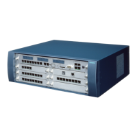
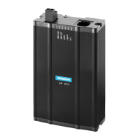
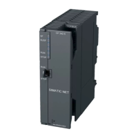
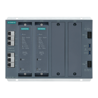
Figure 3-59 PFT1 (S30777-Q539-X) and PFT4 (S30777-Q540-X) board
assignment
3.4.8 REAL
Functional areas
The tasks of the REAL board (S30807-Q5913-X) in Hicom 150 E OfficePro are divided into two
functional areas (see Figure 3-61):
Relay (REAL)
Four individual, controllable relays (K1 to K4) are available for special connections. The relays
are energised by means of the CBMOD board via the REAL socket X05 connecting cable. The
switch contacts for all relays are floating and protected by surge protectors.
In addition, a - 48 V line protected by means of a PTC resistor is routed to the MDFU/MDFU-E
and can be used there for external applications (max. 80 mA).
ALUM trunk failure transfer (REAL)
This feature is implemented by two relays (K5, K6) with two switch contacts each. An analog
trunk is transferred from the system to an analog telephone in the event of a power failure or
system restart/reload. The line's loop current is monitored to prevent an existing trunk call from
being disconnected when the power returns.
The relays are activated in normal mode:
- The trunk is connected to the line trunk module.
- The subscriber line is connected to the SLA16 analog line module.
The relays are deactivated in the event of a power failure or during a restart/reload (low
http://cmweb01.mch.pn.siemens.de/e_doku/en/h150/h15/30/sh/2/15_33.htm (8 of 16) [06/04/2000 13:04:11]
 Loading...
