Programmer’s Guide BCM5722
10/15/07
Broadcom Corporation
Document 5722-PG101-R Receive Return Rings Page 66
RECEIVE RULES SETUP AND FRAME CLASSIFICATION
The BCM5722 Ethernet controller has a feature that allows for the classification of receive packets based on a set of rules.
The rules are determined by the host software and then input into the BCM5722 Ethernet controller.
A packet can be accepted or rejected based on the rules initialized into two rules register areas. The packets can also be
classified into groups of packets of higher to lower priority using the rules registers. This occurs when the packet is directed
to a specific return ring. Return rings 1–4 have an inherent priority associated with them. The priority is from lowest ring
number to highest ring number; return ring 1 being the highest priority ring and return ring 4 being the lowest. The
implementation of priority class is based on how many rings the host software has initialized and made available to the
BCM5722 Ethernet controller. As packets arrive, the BCM5722 Ethernet controller may classify each packet based on the
rules. When the host services the receive packet, it can service the lower numbered rings first.
A rule can be changed by first disabling it by setting 0 into Enable bit (bit 31) in Receive BD Rules Control register (see
Table 32). Wait about 20 receive clocks (rx_clock) and then re-enable it when it is programmed with a new rule. Otherwise,
changing the rules dynamically during runtime may cause the rule checker to output erroneous results because the rule
checker is a pipelined design and uses the various fields of the rules at different clock cycles.
Receive Rules Configuration Register
The Receive Rules Configuration register (memory offset 0x500–0x503, see Table 31) uses bits 3:7 to specify the ring where
a received packet should be placed into if no rules are met, or if the rules have not been set up. A value of 0 means the
received packet will be discarded. A value of 1–16 specifies a corresponding ring. This ring should be initialized to at least
a value of 1 if the rules are not being used to ensure that all received packets will be DMAed to return ring 1.
Receive List Placement Rules Array
The Receive List Placement Rules Array (memory offset 0x480–0x4ff) is made up of 16 combined element registers. The
combined element is actually two 32-bit registers called the Receive BD Rules Control register (see Table 32) and the
Receive BD Rules Value/Mask register (see Table 33). The element can be looked at as a single 64-bit entity with a Control
part and Value/Mask part since they use a single element. Bit 26 of the control part determines how the value/mask part is
used. The Receive BD Rules Value/Mask register can be used as either a 32-bit left-justified Value or a 16-bit Mask followed
by a 16-bit Value.
Table 31: Receive Rules Configuration Register
Bits Field Access
31:8 Reserved RO
7:3 Specifies the default class (ring) if no rules are matched R/W
2:0 Reserved RO
Note: Receive rules cannot be used to match VLAN headers because the VLAN tag is stripped from the Ethernet
frame before the rule checker runs.
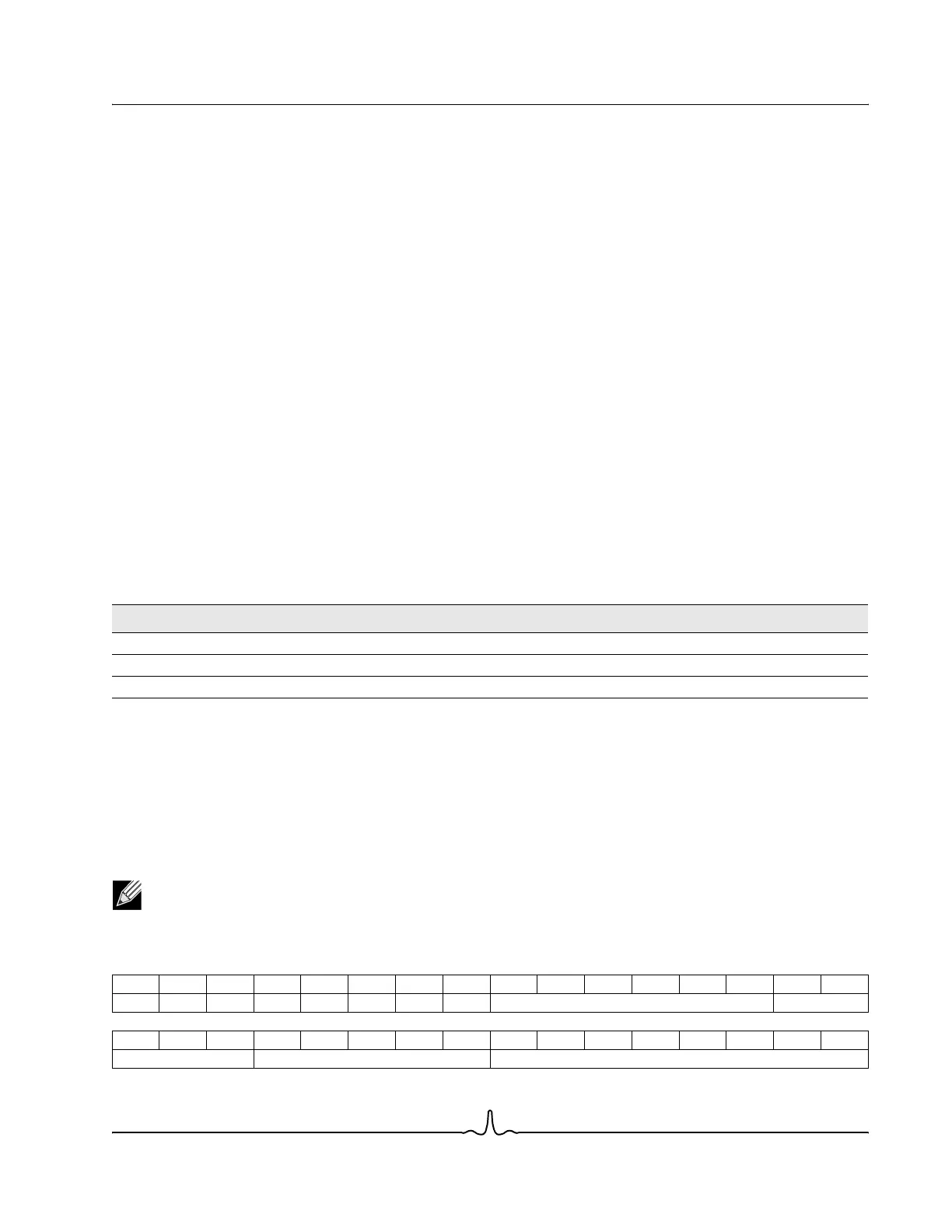
Table 32: Receive BD Rules Control Register
31 30 29 28 27 26 25 24 23 22 21 20 19 18 17 16
E & P1 P2 P3 M D Map Reserved Op
1514131211109876543210
Header Class Offset