EasyManuals Logo

IBM TS3310 User Manual

IBM TS3310
531 pages
To Next Page IconTo Next Page
To Previous Page IconTo Previous Page
Page #255 background imageLoading...
Page #255 background image
4. Open the I/O Station door then the Access Door of the control module to
expose the control module alignment pin behind the Access Door.
5. Push the control module onto the lower expansion module.
6. Twist the control module alignment pin (1 in Figure 8-8 on page 8-11) to
unlock it from the up position.
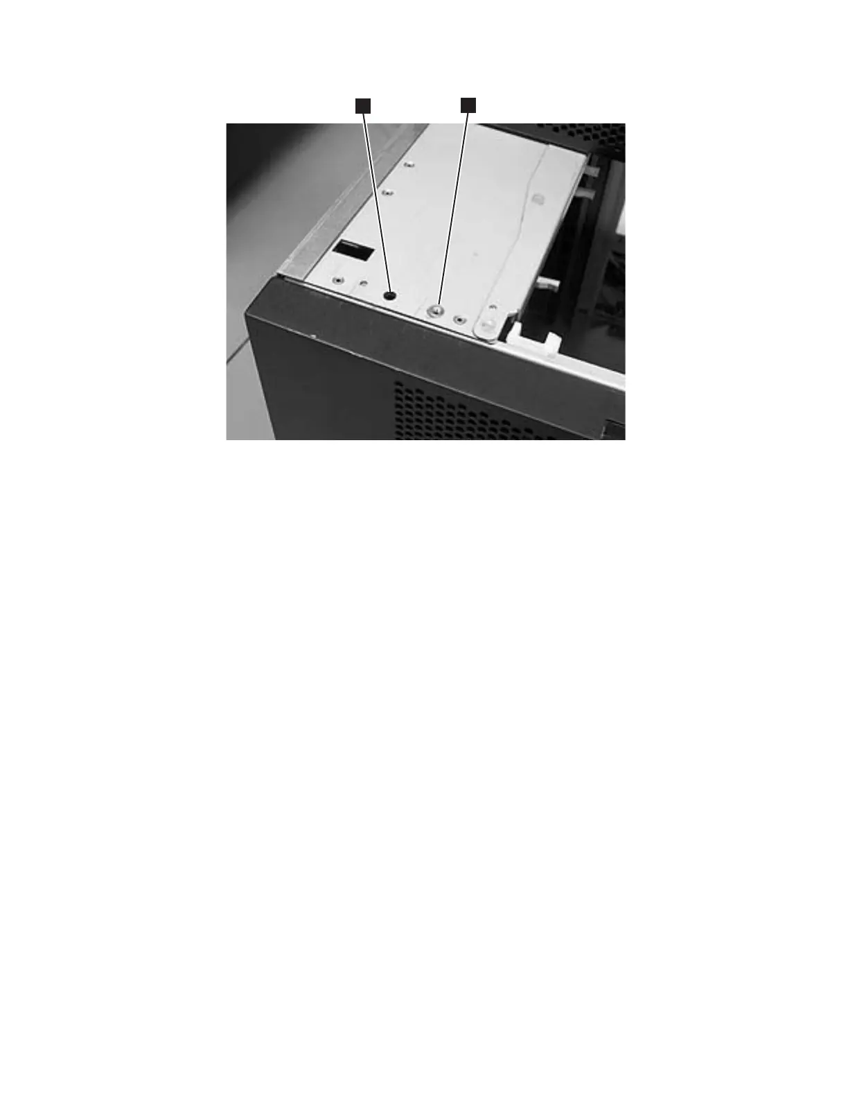
7. Adjust the control module's position on top of the expansion module until the
control module alignment pin drops into the alignment pin receptacle (1 in
Figure 8-10) in the lower expansion module.
8. Tighten the front thumb screw (2 in Figure 8-8 on page 8-11) to secure the
front of the control module to the lower expansion module (2 in
Figure 8-10).
9. Open the I/O Station door and tighten the other front thumb screw.
a66mi0
17
1
2
Figure 8-10. Alignment pin and front thumb screw receptacles
Chapter 8. Add, Check, Adjust, Remove, and Replace Procedures 8-13

Table of Contents

Questions and Answers:

Question and Answer IconNeed help?

Do you have a question about the IBM TS3310 and is the answer not in the manual?

IBM TS3310 Specifications

General IconGeneral
Form FactorRack-mountable
Tape TechnologyLTO Ultrium
Product TypeTape Library
InterfaceFibre Channel
ExpansionExpandable with additional modules
Supported Tape TechnologyLTO Ultrium 5, LTO Ultrium 6
Weight120 lb (54.4 kg) (fully configured)
Power SupplyDual redundant power supplies
Operating Temperature41°F to 95°F (5°C to 35°C)
Non-operating Temperature-40°F to 140°F (-40°C to 60°C)
Humidity20% to 80% non-condensing

Related product manuals