3. While pinching the gear rack locking mechanism, push up on the gear rack,
then release your hold on the locking mechanism.
4. Bend the small metal tab (1 in Figure 8-119 on page 8-108) in slightly to
prevent the gear rack from moving down too far.
5. Replace the covers of the module, if necessary.
6. Return the module to its correct, upright position.
Removing Internal Cables and Boards
Special tools required for this procedure:
v T6 Torx wrench for D-Shell connectors on BCB cables
v T8 Torx wrench for BCB board
v 5 mm (3/16 inch) wrench for the stand-off behind cable spool assembly
v 4.5 mm (3/16 inch) wrench for DSIB board
Important:
v Prior to replacing all of the internal cables and boards you should
visually check, and reseat if necessary, all of the internal connectors.
(see “Internal Cables” on page 7-32).
v It may not be necessary to replace all of the cables and boards in this
procedure. Depending on your failure symptoms and discussions
with Technical Support, you may only have to replace a portion of
these parts.
1. Perform “Preparing a Library or Library Module for Repairs” on page 8-4.
1
2
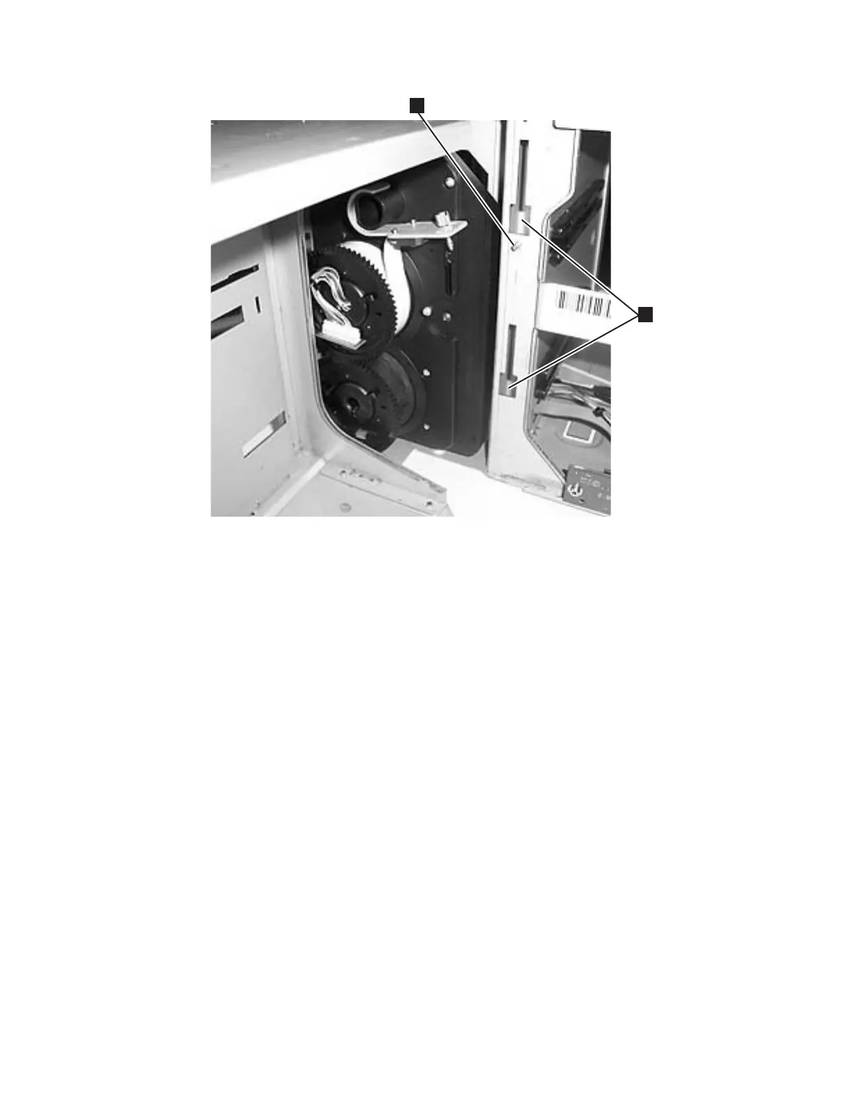
a66mi013
Figure 8-122. Rear gear rack location on chassis
Chapter 8. Add, Check, Adjust, Remove, and Replace Procedures 8-111