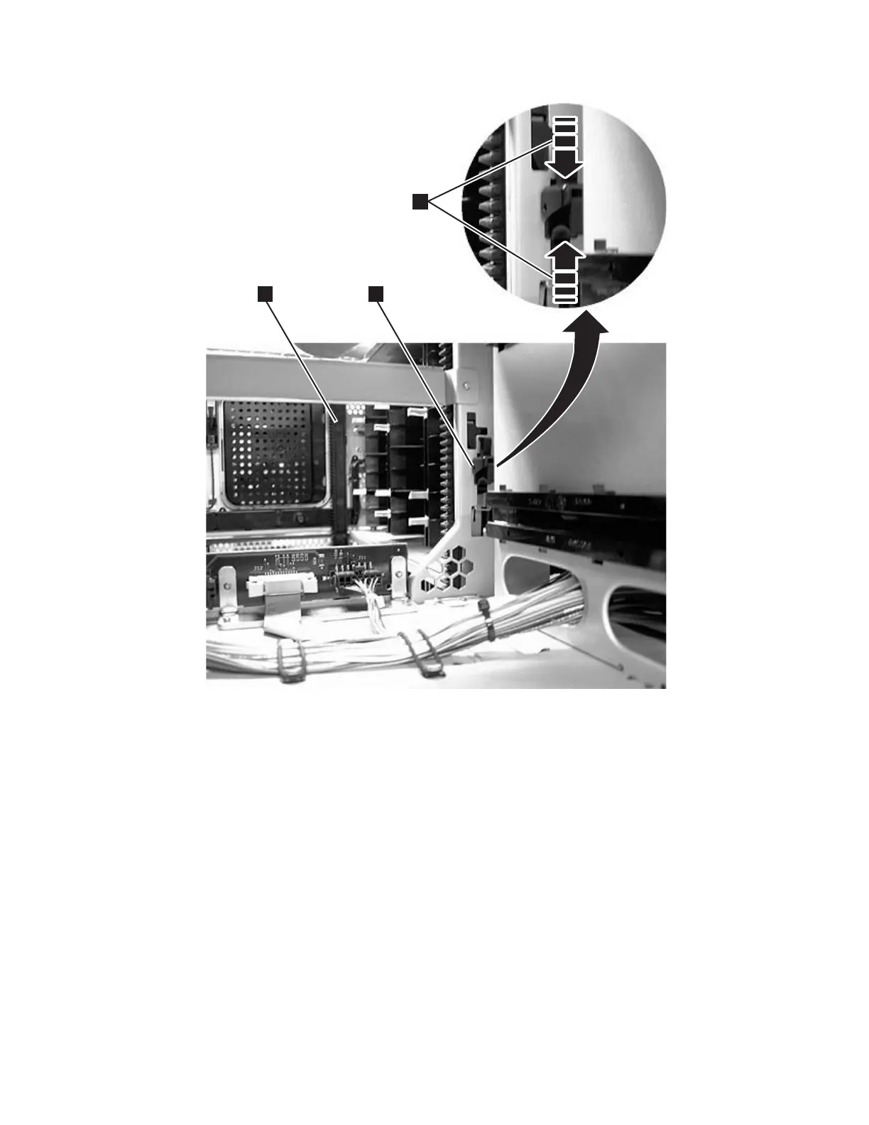
3. Disengage the rear (1 in Figure 8-2) and front (3 in Figure 8-2) gear racks
in the control module. While pinching the gear rack locking mechanism (2
in Figure 8-2) , push the gear rack up until it locks in place. To release the
gear rack and move it up, follow the steps below.
a66mi007
1
2
3
Figure 8-2. Gear racks and gear rack locking mechanism
Chapter 8. Add, Check, Adjust, Remove, and Replace Procedures 8-7
|
|