10. Rotate the threader motor worm gear (4 in Figure 8-141 on page 8-131) to
turn the threader mechanism gear (6 in Figure 8-141 on page 8-131)
counterclockwise. This moves the LBA out of the cartridge and past the
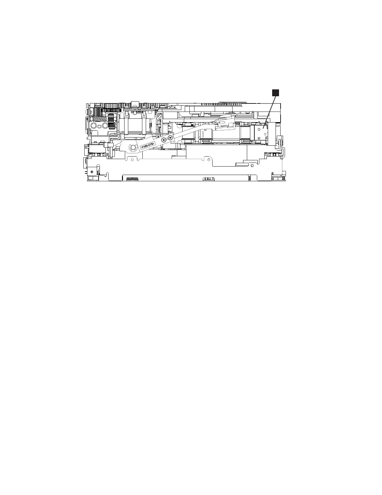
read/write head. Stop this rotation when the LBA is near the tape guide roller
nearest the rear of the drive shown as 1 Figure 8-142.
11. Continue rotating the loader motor worm gear (1 in Figure 8-141 on page
8-131) until the rotator stub (3 in Figure 8-141 on page 8-131) is positioned
as shown. Notice that the rotator stub (3 in Figure 8-141 on page 8-131) is
nearly aligned with the cartridge loader tray guide bearing (2 in
Figure 8-141 on page 8-131).
12. Remove the cartridge from the cartridge loader tray.
13. Reassemble the drive by reversing the procedure in Step 5 in “Beginning
Procedure” on page 8-123.
14. Refer to the appropriate procedure to install the new drive and return the
failed drive.
No Apparent Failure or Damage to Tape
1. Set the drive on its left side with the head and tape path facing up.
a82ru010
1
Figure 8-142. Leader Block Assembly (LBA)
8-132 TS3310 Tape Library Maintenance Information
 Loading...