v Storage Column
v Cable Spool
v Gear Rack
v Internal Cables/Boards
v Drive Power Fuse
Y-axis/Picker Assembly
The Y-axis/Picker Assembly houses the Y Motor and moves the Picker and Bar
Code Scanner within the library.
Removing the Y-axis/Picker Assembly
1. Perform “Preparing a Library or Library Module for Repairs” on page 8-4.
2. Perform one of the following procedures:
v “Removing a 5U Library (Control Module) from a Rack” on page 8-4
v “Removing a Control Module from a Standalone or Rack-mounted Library
(14U or larger)” on page 8-5
3. Remove the top cover of the control module, if necessary.
4. Open the I/O Station door then the Access Door to access the Y-axis/Picker
Assembly.
5. Optionally, remove the I/O Station from the control module for easier access.
See “Removing an I/O Station” on page 8-35.
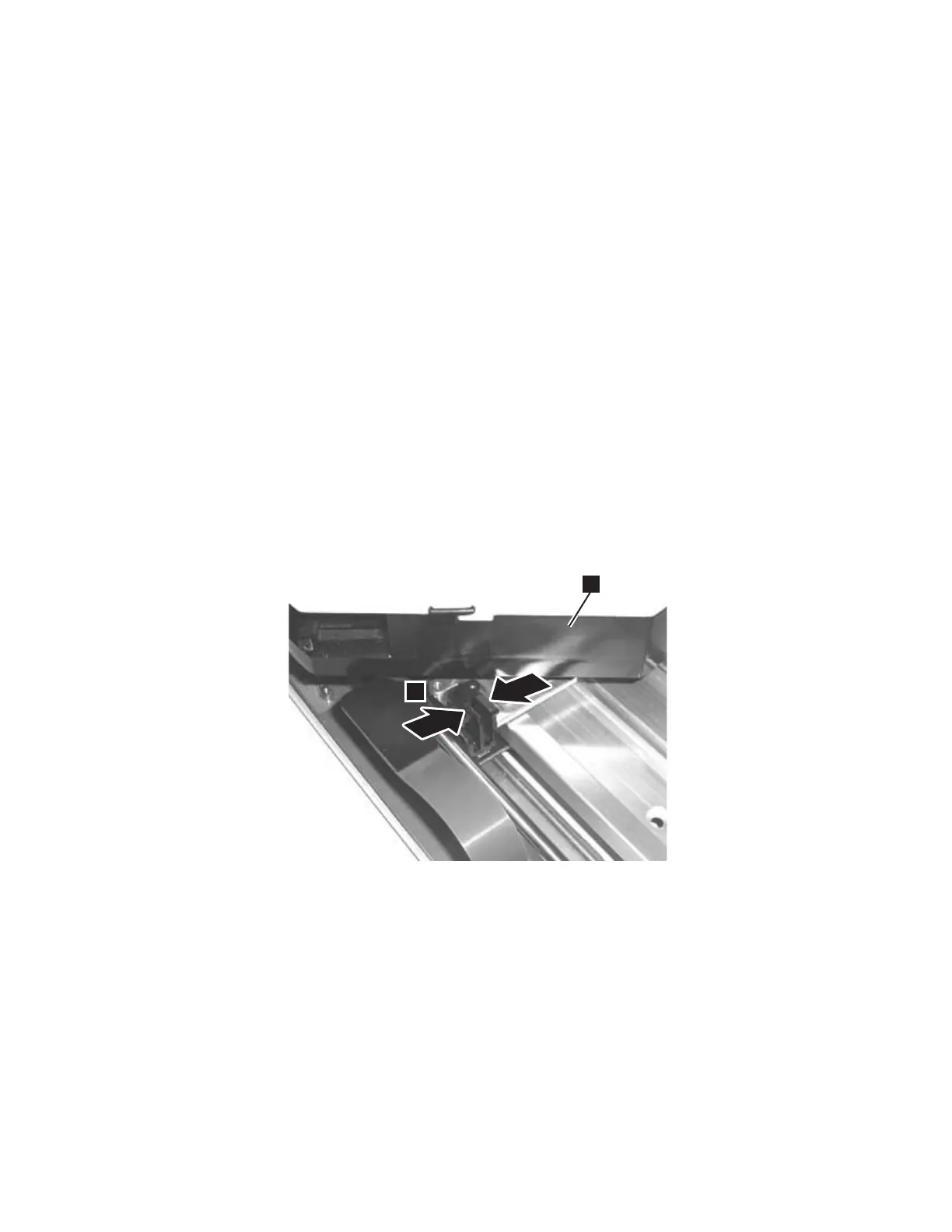
6. Raise the Y-axis/Picker Assembly to the top of the library and carefully lift it
out. Be careful not to damage the Cable Spool flat cable (2 in Figure 8-56 on
page 8-56). Set the Y-axis/Picker Assembly on top of the control module and
loosen the thumbscrew (1 in Figure 8-56 on page 8-56) to disconnect the cable
spool.
1
2
a66mi002
Figure 8-55. Flat cable connector
Chapter 8. Add, Check, Adjust, Remove, and Replace Procedures 8-55