Replacing the Y-axis/Picker Assembly
1. Ensure all gear racks are properly positioned and that they contain NO GAPS
between units in the library.
2. Set the Y-axis/Picker Assembly on top of the control module as shown in
Figure 8-56 on page 8-56.
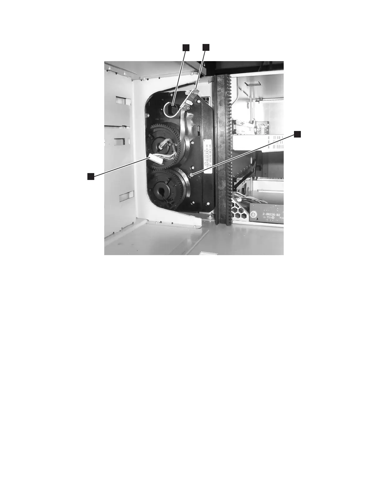
3. Remove the Cable Spool connector (3 in Figure 8-57) from the black plastic
peg (2 in Figure 8-57).
4. Carefully lift the Cable Spool connector.
5. Tighten the thumb screw to connect the spooler cable to the Y-axis/Picker
Assembly (1 in Figure 8-56 on page 8-56).
6. Lower the Y-axis/Picker Assembly by tilting its gears at a 45° angle onto the
top of the front and rear gear racks (see Figure 8-58 on page 8-58and
Figure 8-59 on page 8-59). BE VERY CAREFUL TO START BOTH
Y-AXIS/PICKER ASSEMBLY GEARS TOGETHER TO ENSURE THE
Y-AXIS/PICKER ASSEMBLY IS LEVEL. After lowering the Y-axis/Picker
Assembly a few teeth, verify that the Y-axis/Picker Assembly is level with
the library chassis. If it is not level, remove the Y-axis/Picker Assembly and
reinsert.
a66mi012
4
3
1
2
Figure 8-57. Cable Spool (with storage columns removed)
Chapter 8. Add, Check, Adjust, Remove, and Replace Procedures 8-57