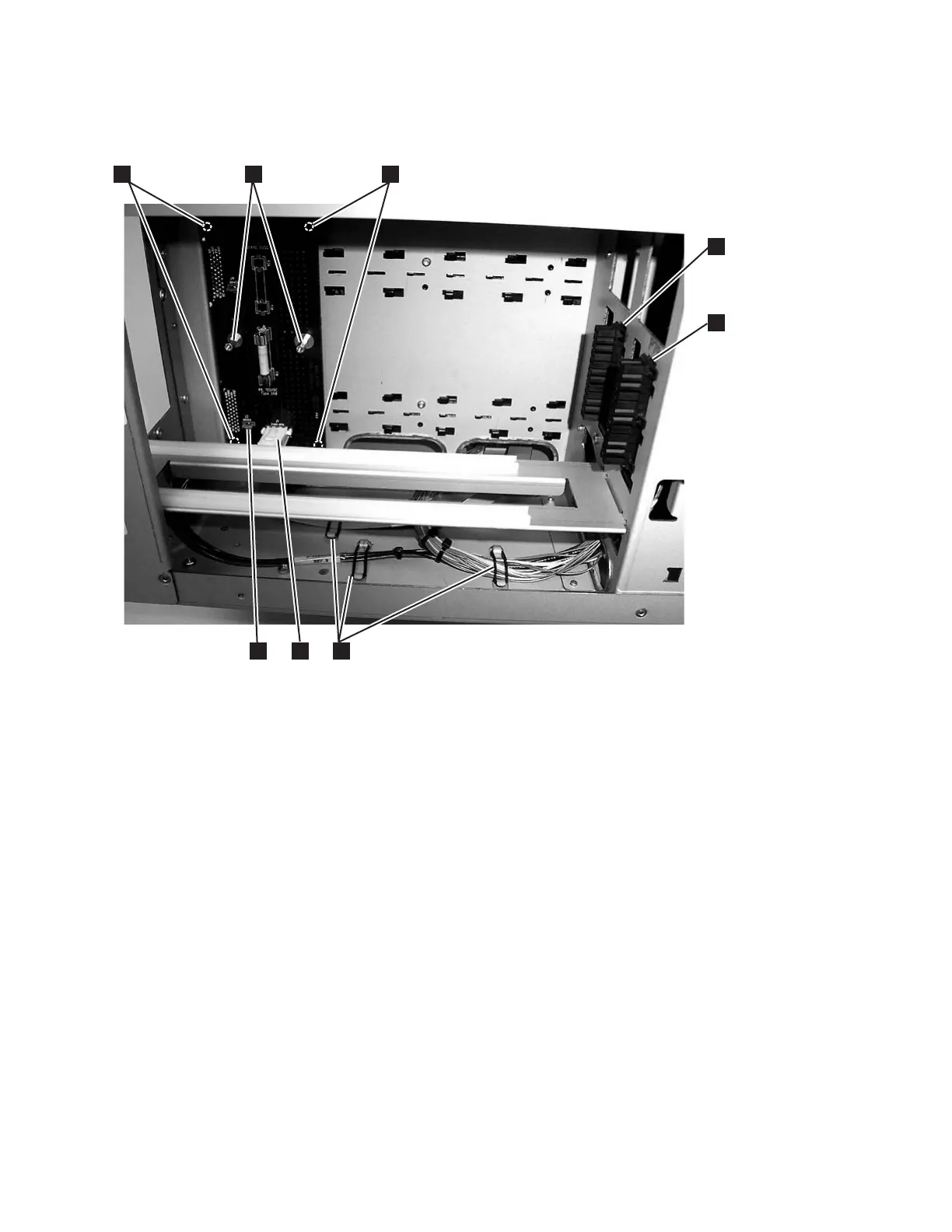
5. Visually check, and reseat if necessary, all of the connectors on the Drive Sled
Interface Board (DSIB). See 7 and 8 in Figure 7-14.
6. Visually check, and reseat if necessary, all of the connectors on the Robot
Assembly.
v For the Robot Assembly, see 1, 2and 3 in Figure 7-15 on page 7-36.. For
the Picker Assembly, see 1 in Figure 7-16 on page 7-37.
a66mi102
1
3
2
4
5
6
7
8
Figure 7-14. Drive Sled Interface Board connectors (side cover removed)
Chapter 7. Service Procedures 7-35