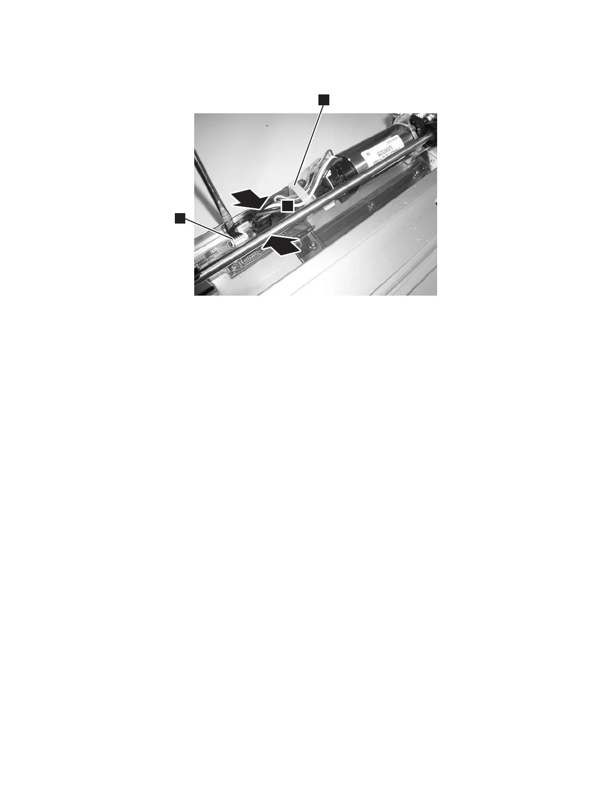
4. Connect the large black connector. See Figure 8-69.
a. Pinch the latch on the cable connector (1 in Figure 8-69).
b. Carefully plug in the connector.
5. Engage the cable retention clip.
6. Perform “Replacing the M2 Robot Assembly” on page 8-69.
7. Perform one of the following procedures:
v “Replacing a 5U Library (Control Module) in a Rack” on page 8-5
v “Replacing a Control Module in a Standalone or Rack-mounted Library (14U
or larger)” on page 8-12
8. Perform “Returning a Library or Library Module to Normal Operations after
Repairs” on page 8-4.
M2 Robot Assembly
The M2 Robot Assembly houses the Y Motor, Robot Controller Board, and the
Picker.
Removing the M2 Robot Assembly from the Library
1. Perform “Preparing a Library or Library Module for Repairs” on page 8-4.
2. Perform one of the following procedures:
v “Removing a 5U Library (Control Module) from a Rack” on page 8-4
v “Removing a Control Module from a Standalone or Rack-mounted Library
(14U or larger)” on page 8-5
3. Remove the top cover of the control module, if necessary.
4. Open the I/O Station door then the Access Door to access the M2 Robot
Assembly.
5. Optionally, remove the I/O Station from the control module for easier access.
See “Removing an I/O Station” on page 8-35
6. Manually lift the M2 Robot Assembly, raise it along the track, and carefully lift
it out. Be careful not to damage the Cable Spool flat cable (2 in Figure 8-70
on page 8-68). Set the M2 Robot Assembly on top of the library and loosen the
a66mi004
1
2
3
Figure 8-69. Y motor connector
Chapter 8. Add, Check, Adjust, Remove, and Replace Procedures 8-67