d. Remove the black protective cover from the back of the Operator Panel.
e. Remove cable connectors J36 (see 3 in Figure 8-125 on page 8-114), J35
(see 5 in Figure 8-125 on page 8-114), and J32 (see 7 in Figure 8-125 on
page 8-114) from the Operator Panel board.
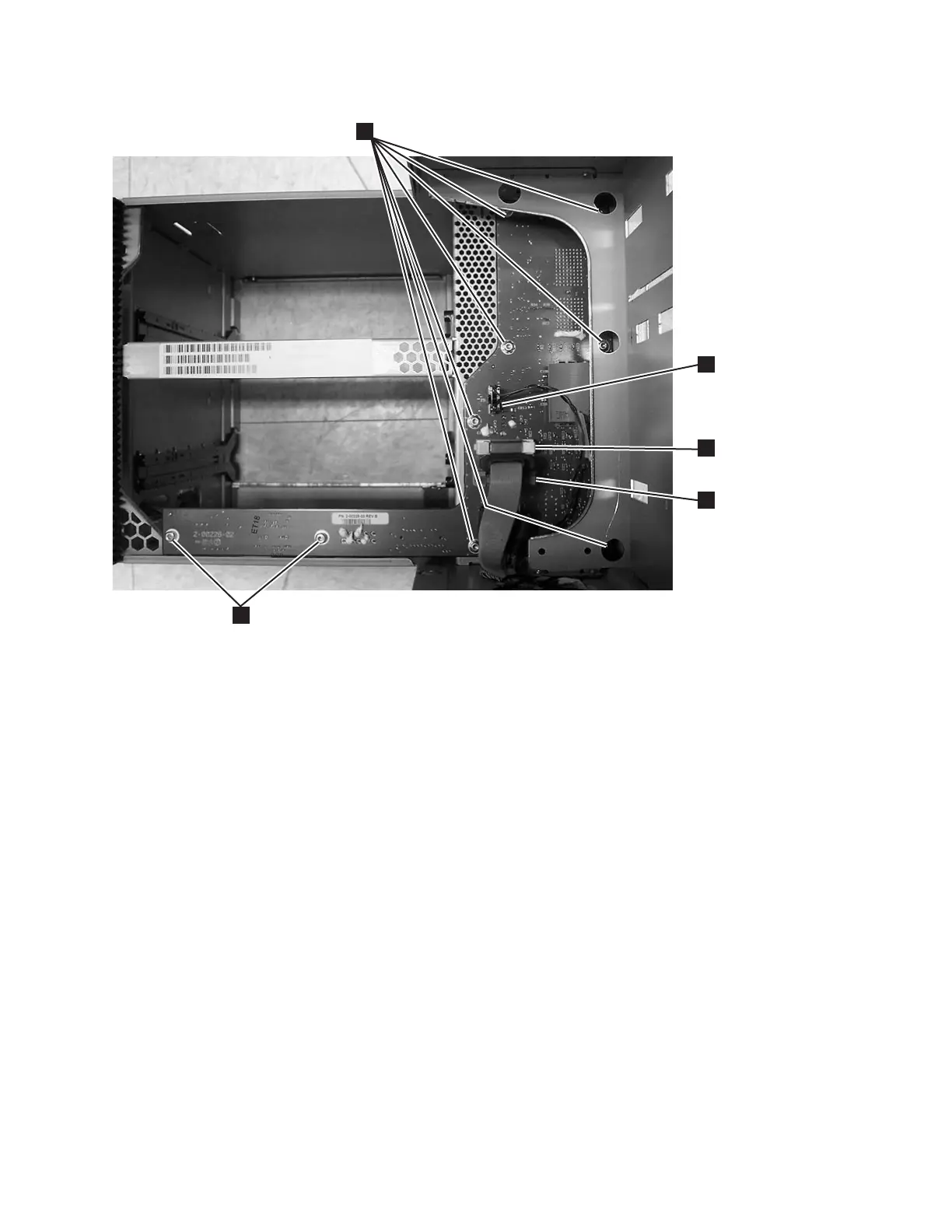
a66mi101
1
3
2
4
5
Figure 8-124. Backplane Connector Board (BCB), Front View
Chapter 8. Add, Check, Adjust, Remove, and Replace Procedures 8-113