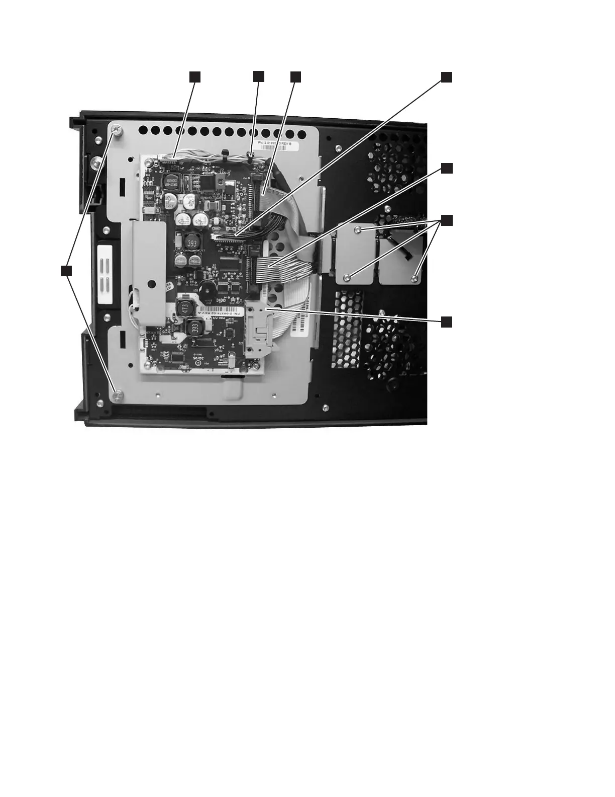
f. Remove the 3 screws (see 6 in Figure 8-125) from the cable retainer bracket
on the back of the door.
g. Remove the 4 screws (see 2 in Figure 8-126 on page 8-115) from the front
of the door, holding the long plastic cable guide to the door.
Note: The mounting holes in the new plastic cable guide may not match
correctly with the screw holes in the door. If they do not match
correctly, it will be necessary to transfer the plastic guide from the
old cable assembly to the new cable assembly. Cut the cable ties to
remove the plastic guides from both the old cable and the new cable.
Use the new cable ties in the FRU kit to attach the old guide to the
new cable.
a66mi088
2
3
4
1
5
6
8
7
Figure 8-125. Operator Panel Cable Connectors
8-114 TS3310 Tape Library Maintenance Information