3. Tighten the T10 Torxretaining screw (4 in Figure 8-115 on page 8-104) until
the Cable Spool Assembly is secured to the enclosure.
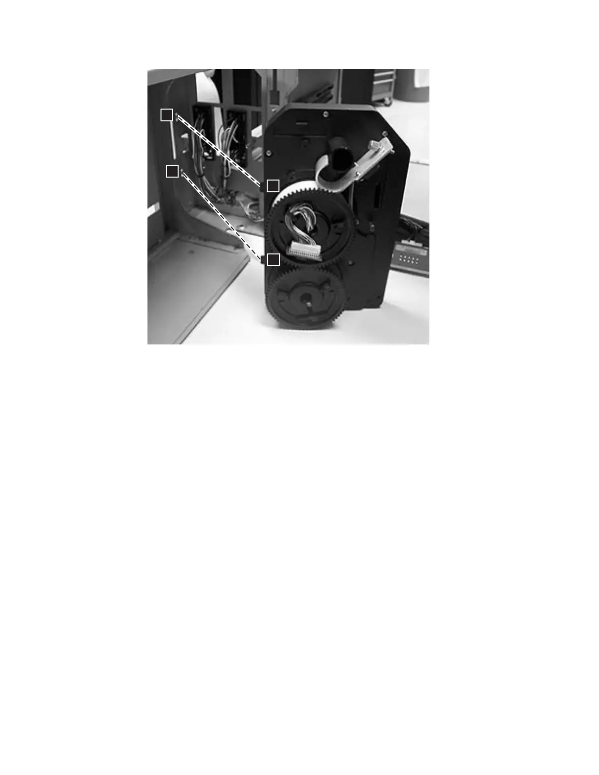
4. Connect the Cable Spool connector (1 in Figure 8-114 on page 8-103) to the
J11 connector on thedistribution board.
5. Replace the Storage Columns. See “Replacing a Storage Column” on page 8-97.
6. Replace the Y-axis/Picker Assembly. See “Replacing the M2 Robot Assembly”
on page 8-69.
7. If they were removed, replace the top cover and left side cover.
8. If your library is installed in a rack, perform one of the following procedures:
v “Replacing a 5U Library (Control Module) in a Rack” on page 8-5
v “Replacing a Control Module in a Standalone or Rack-mounted Library (14U
or larger)” on page 8-12
9. Perform “Returning a Library or Library Module to Normal Operations after
Repairs” on page 8-4.
Gear Rack
The Y-axis Assembly uses the Gear Racks (one in front, one in back) to move the
Picker and Bar Code scanner within the library.
Removing a Front Gear Rack
1. Lay the library module on the left side (from front).
2. Remove the bottom cover of the module, if necessary.
3. There is a small metal tab in the chassis frame (1 in Figure 8-118 on page
8-107) that prevents the gear rack from falling down too far when the locking
mechanism is released. Bend the tab out slightly so the gear rack can be
removed.
2
1
a66mi0
11
2
1
Figure 8-117. Cable Spool Assembly tabs
8-106 TS3310 Tape Library Maintenance Information
|