EasyManuals Logo

IBM TS3310 User Manual

IBM TS3310
531 pages
To Next Page IconTo Next Page
To Previous Page IconTo Previous Page
Page #357 background imageLoading...
Page #357 background image
h. Carefully remove the cable assembly from the enclosure.
7. Remove the cable assemblies between the Power Supplies, the Drive Sled
Interface Board (DSIB), and the Backplane Connector Board (BCB) by following
these procedures:
a. Remove the “Cable Spool Assembly” on page 8-100.
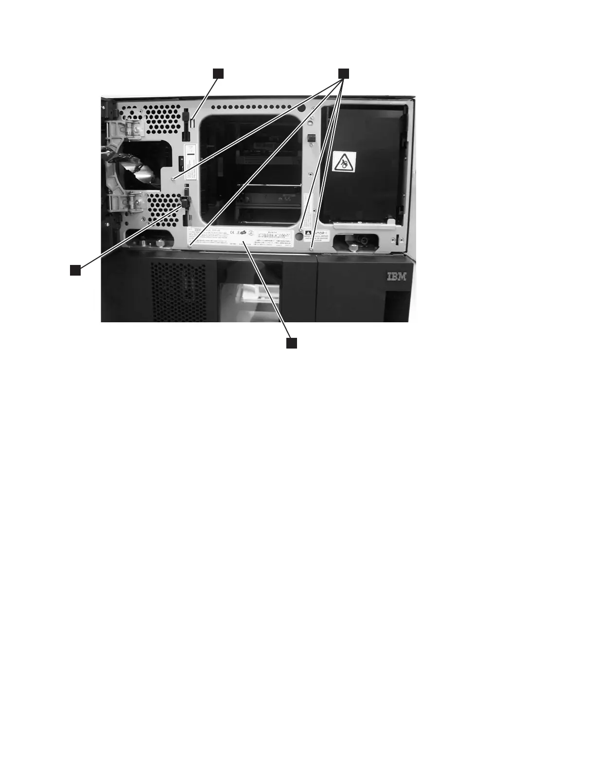
b. Remove the hex stand-off (see 1 in Figure 8-127 on page 8-116) from
behind the Cable Spool Assembly. This requiresa5mm(3/16-inch) wrench.
a66mi074
1
3
4
2
Figure 8-126. Four screws on front of door and plastic cable guide
Chapter 8. Add, Check, Adjust, Remove, and Replace Procedures 8-115

Table of Contents

Questions and Answers:

Question and Answer IconNeed help?

Do you have a question about the IBM TS3310 and is the answer not in the manual?

IBM TS3310 Specifications

General IconGeneral
Form FactorRack-mountable
Tape TechnologyLTO Ultrium
Product TypeTape Library
InterfaceFibre Channel
ExpansionExpandable with additional modules
Supported Tape TechnologyLTO Ultrium 5, LTO Ultrium 6
Weight120 lb (54.4 kg) (fully configured)
Power SupplyDual redundant power supplies
Operating Temperature41°F to 95°F (5°C to 35°C)
Non-operating Temperature-40°F to 140°F (-40°C to 60°C)
Humidity20% to 80% non-condensing

Related product manuals