Important: If the Control Module is at the bottom of the library, the gear racks
should remain locked in the UP position. Skip step 12 and step 13
if the Control Module is at the bottom of the library. If the Control
Module is not at the bottom of the library, perform step 12 and
step 13.
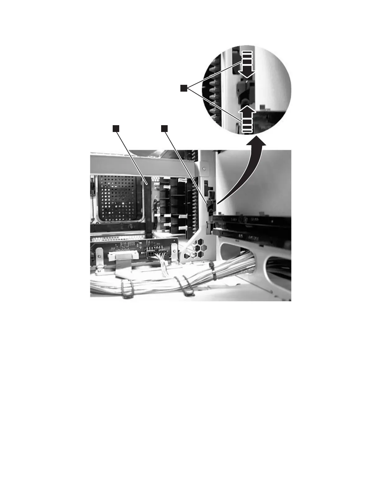
12. Engage the rear (1 in Figure 8-12) and front (3 in Figure 8-12) gear racks
in the control module. While pinching the gear rack locking mechanism (2
in Figure 8-12), push the gear rack down until it locks in place and no gaps
appear between the front and rear gear racks in the control module and
expansion module.
13. To release the gear rack and move it down, follow these steps.
v Engage the Y-rails of each module in your library configuration. Ensure that
the Y-rails are properly aligned and the thumbscrews are tightened.
a66mi007
1
2
3
Figure 8-12. Gear racks and gear rack locking mechanism
Chapter 8. Add, Check, Adjust, Remove, and Replace Procedures 8-15
|
|
|
|
|
|
|
|
|