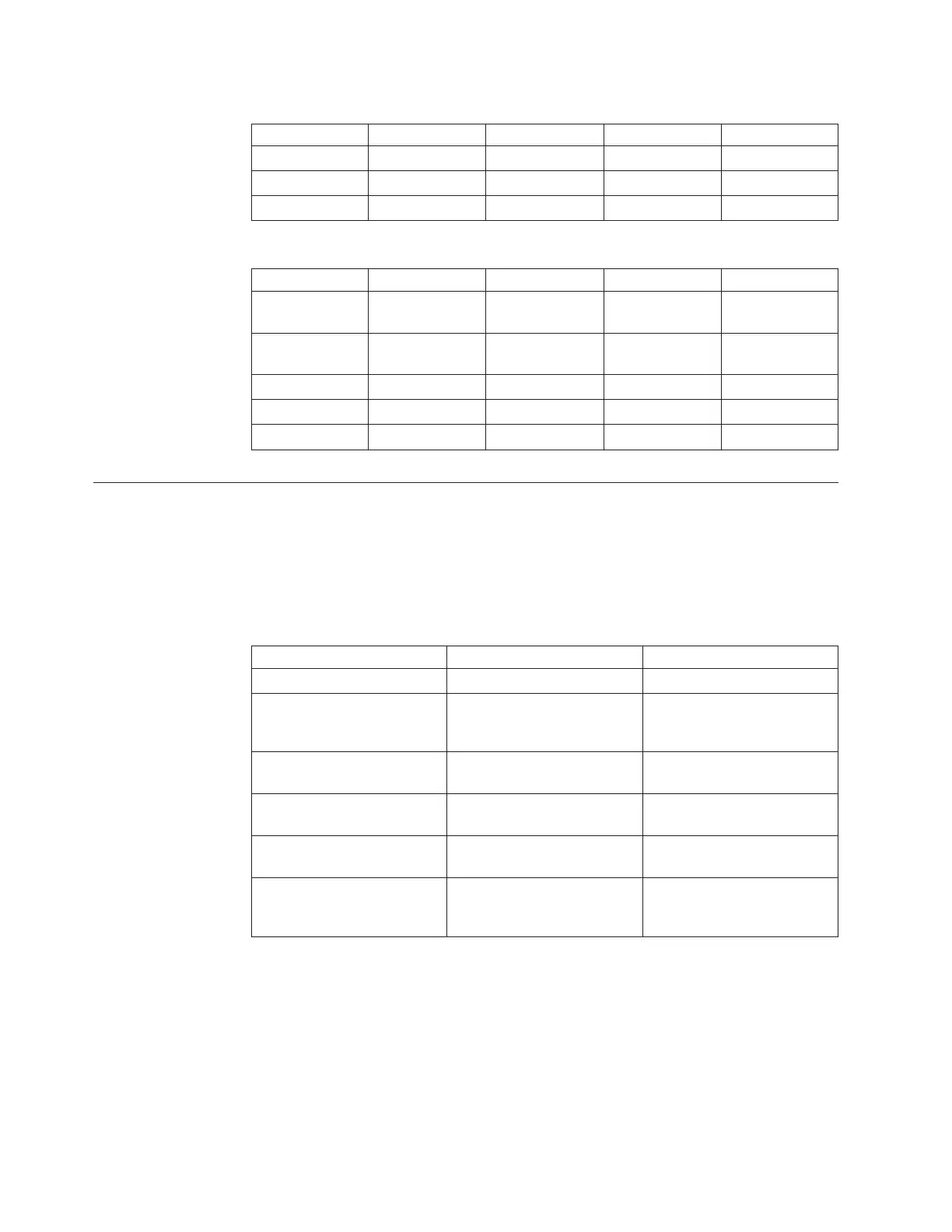
Table C-1. Control module (CM) power requirements (continued)
Item Volts Amps DC Watts AC Watts
Total 332.23 390.83
Power Supply 350 watts
Table C-2. Typical expansion module (EU) power requirements
Item Volts Amps DC Watts AC Watts
Drive sleds -
4x50
200 235.29
Drive Sled 1x1
(10w)
40 23.5
Total 320 352.91
Power Supply 350 watts
Interpreting Library Diagrams
Each component has a specific role that is critical in the library's overall
performance. Components serve either a logic (i.e., processes data) or interconnect
(i.e., carries signals between components) function within the library.
The following table lists the library components, their module location(s), and their
overall function (i.e., logic or interconnect):
Component Module Function
Library Control Blade (LCB) Control module Logic
Backplane Connect boards
(BCB1, BCB2, BCB3)
Control module (BCB1) &
expansion modules (BCB2 &
BCB3)
Interconnect
Power supply Control module & expansion
module (with drives)
Power
Servo & Motor Driver Boards
(SMD1 & SMD2)
Control module Logic (SMD1) & interconnect
(SMD2)
Door & Import/Export Board
(DIEB)
Control module Logic
Drive Sled Interconnect
Boards (DSIB1 & DSIB2)
Control module (DSIB1) &
expansion module (DSIB1 or
DSIB2)
Interconnect
Library Control Blade (LCB)
The LCB1 is a critical logic component of the library. It is only located in the
control module. The LCB1 serves as the "brain" or primary control board, for
library operations. It communicates with the host server's backup application and
issues commands in communicating with various library components:
v Issues motion commands for the servo and motor driver board to execute over
the LCB1 to SMD1/SMD2 communication interface
v Library CAN network connects the LCB1 to the motion processor on SMD1
C-2 TS3310 Tape Library Maintenance Information
 Loading...