Replacing the Operator Panel
To replace the Operator Panel, complete the removal procedure in reverse. For the
last step, perform “Returning a Library or Library Module to Normal Operations
after Repairs” on page 8-4.
Removing/Replacing the Power Switch/LED Board Assembly
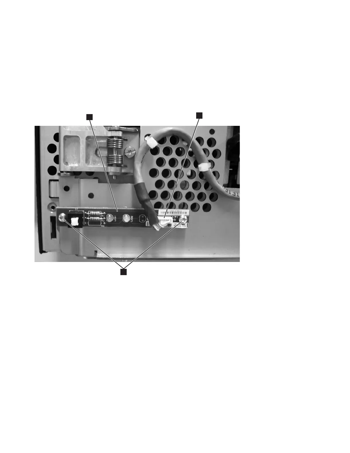
The Power Switch/LED Board Assembly (1 in Figure 8-30) contains the power
ON/OFF button, power ON LED, and Operator Attention LED.
Removing the Power Switch/LED Board Assembly
1. Perform “Preparing a Library or Library Module for Repairs” on page 8-4.
2. Perform “Removing the Access Door Bezel” on page 8-27.
3. Disconnect the small white connector (2 in Figure 8-30).
4. Remove the two screws (3 in Figure 8-30).
5. Remove the Power Switch/LED Board Assembly from the Control Module.
Note that the FRU kit for this assembly contains the cable and cable ties. If you
suspect the cable may be failing, replace it also.
Replacing the Power Switch/LED Board Assembly
1. Perform “Removing the Power Switch/LED Board Assembly” in reverse order.
2. Perform “Returning a Library or Library Module to Normal Operations after
Repairs” on page 8-4.
a66mi084
2
3
1
Figure 8-30. Power Switch/LED Board Assembly
8-32 TS3310 Tape Library Maintenance Information