3. Remove the cartridges from the I/O Station to access the screw located on the
backside of the I/O Station door.
4. Remove the screw located on the backside of the I/O Station door.
5. Hold the I/O Station slide assembly in place with one hand and, using your
other hand, pull the I/O Station door directly up to disengage the bolts, and
then pull the door toward you.
6. Set aside the old front bezel.
Replacing the I/O Station Bezel
To replace the I/O Station bezel, perform the remove procedures in reverse order.
For the last step, perform “Returning a Library or Library Module to Normal
Operations after Repairs” on page 8-4.
Removing the Access Door Bezel
1. Perform “Preparing a Library or Library Module for Repairs” on page 8-4.
2. Open the module's I/O Station and Access Doors.
Note: When you open the Access Door, the library becomes disabled (the
Picker assembly does not function). When you later close the Access
Door, the library will function normally.
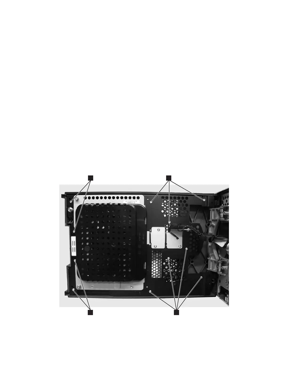
3. Remove the screws located on the backside of the Access Door.
v For the control module (11 screws), see 1 in Figure 8-24.
v For an expansion module (12 screws, see 1 in Figure 8-25 on page 8-28.
a66mi085
1
1
1
1
Figure 8-24. Control module Access Door screw locations
Chapter 8. Add, Check, Adjust, Remove, and Replace Procedures 8-27