Before Removing / Replacing the Operator Panel
Operator panel problems may be caused by loose connectors. Visually check, and
reseat if necessary, all of the connectors on the back of the operator panel
(Figure 8-29 on page 8-31), the connector on the back of the I/O Station locking
mechanism (1 in Figure 8-27 on page 8-30), and the connectors that are located
between the storage column 4 magazine and the back of the Library Control Blade
(2 and 3 in Figure 8-28 on page 8-30).
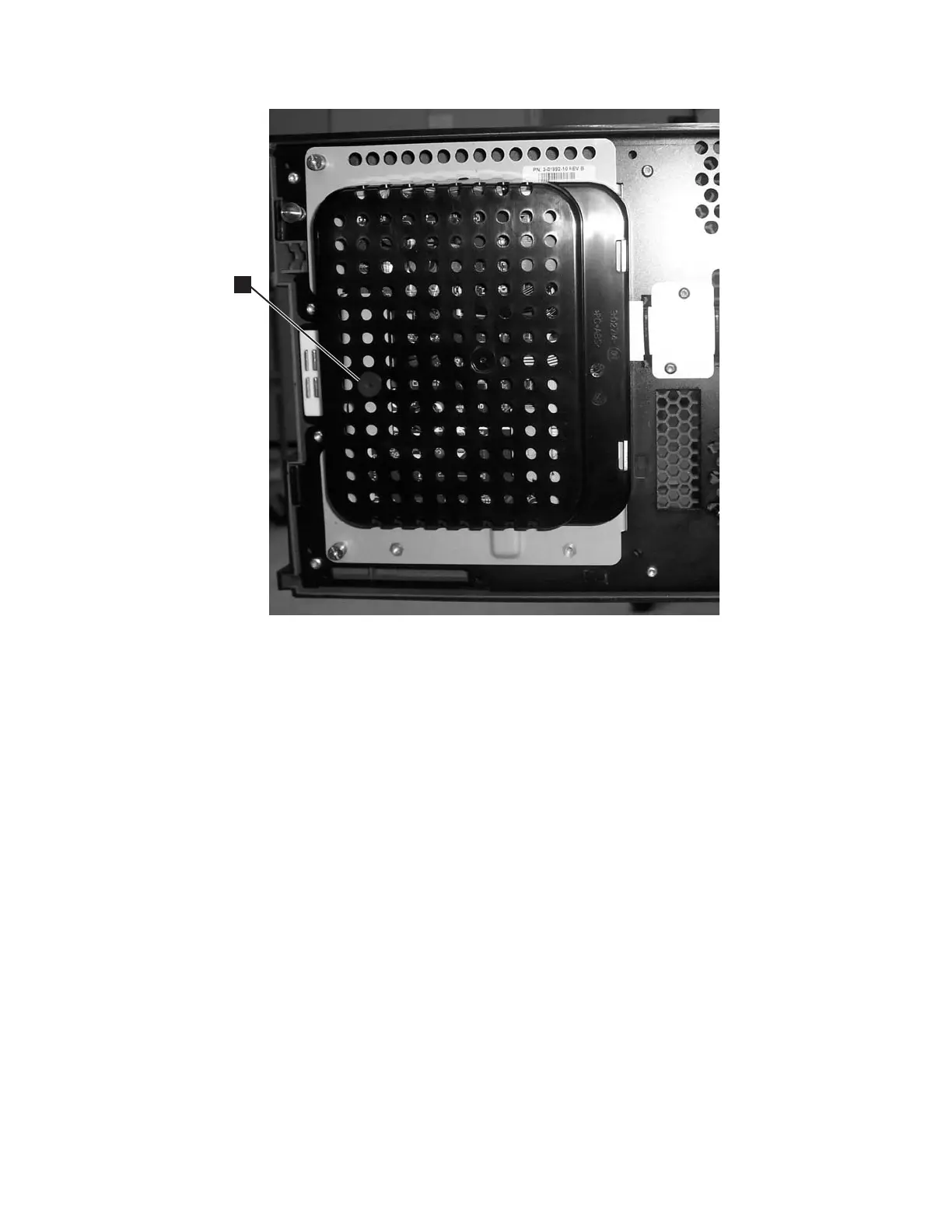
a66mi086
1
Figure 8-26. Operator Panel assembly
Chapter 8. Add, Check, Adjust, Remove, and Replace Procedures 8-29