1
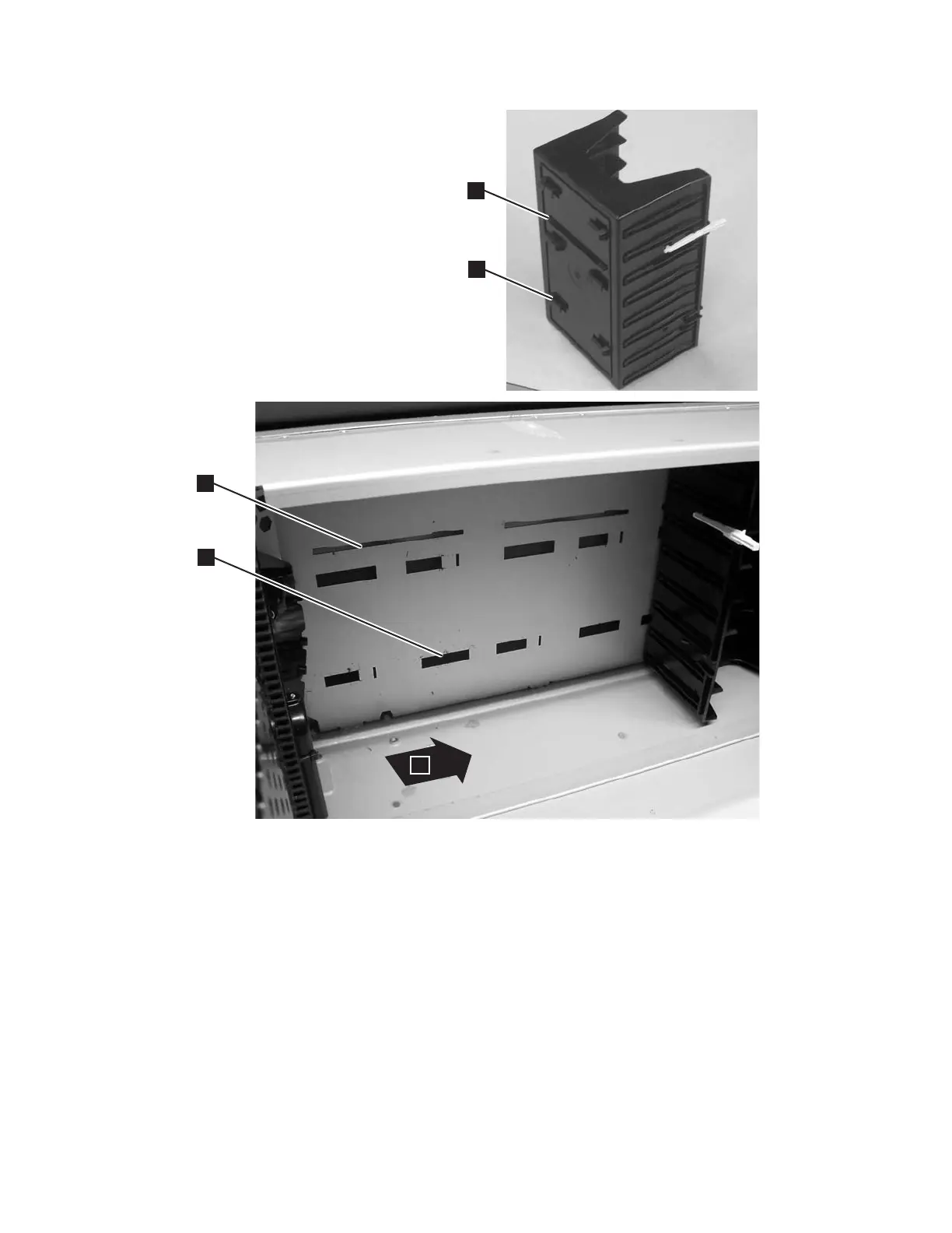
Tab 1 on a storage column
3 Slot 1 in the library chassis wall in a storage
column position
2
Tab 2 on a storage column
4 Slot 2 in the library chassis wall in a storage
column position
3. Ensure correct orientation by inserting:
a. Tab 1 (in Figure 8-112) into slot 3 (in Figure 8-112)
b. Tab 2 (in Figure 8-112) into slot 4 (in Figure 8-112)
4. Push the column towards the rear of the library (5 in Figure 8-112) to engage
the locking tabs on the back of the column.
5. Repeat this procedure for each column.
6. For a 5U library, perform “Replacing the M2 Robot Assembly” on page 8-69.
a66mi019
5
3
4
2
1
Figure 8-112. Replacing a Storage Column
Chapter 8. Add, Check, Adjust, Remove, and Replace Procedures 8-99