Home
IBM
Storage
TS3310
Page 359 (Backplane Connector Board (BCB), Rear)
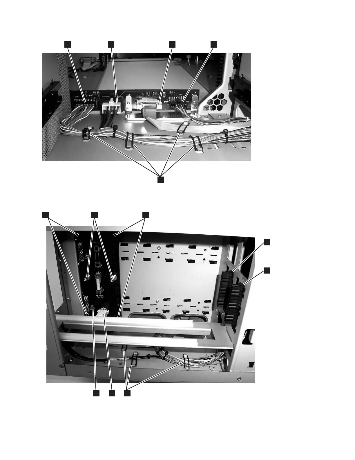
IBM TS3310 - Backplane Connector Board (BCB), Rear; Drive Sled Interface Board (DSIB), Side
531 pages
Manual
Save Page as PDF
To Next Page
To Next Page
To Previous Page
To Previous Page
Loading...
a66mi100
1
3
2
4
5
Figure
8-128.
Backplane
Connector
Board
(BCB),
Rear
View
a66mi102
1
3
2
4
5
6
7
8
Figure
8-129.
Drive
Sled
Interface
Board
(DSIB),
Side
Cover
Removed
Chapter
8.
Add,
Check,
Adjust,
Remove,
and
Replace
Procedures
8-117
358
360
Table of Contents
Main Page
default chapter
5
Registering for Support Notification
5
Sending Us Your Comments
5
7Th Edition
7
Summary of Changes
7
Table of Contents
9
Figures
15
Tables
19
Getting Assistance
21
Preface
21
Related Publications
21
Chapter 1. Start Service
23
Chapter 2. Product Description
29
Front Panel Components
30
Front Panel of a 14U Library
30
Control Module (3576 Model L5B)
31
Expansion Module (3576 Model E9U)
31
I/O Station
31
Library I/O Station Configurations
31
Access Door
32
Operator Panel
32
Power Button
32
Front Panel Leds
32
Rear Panel Components
33
Library Control Blade (LCB)
33
Rear Panel of a 14U Library
33
Tape Drives
34
Power Supply
35
Interior Components
35
Storage Columns
36
Robot Assembly Designs
36
Optional Features
38
M2 Label on the M2 Robot Assembly
38
Power Supply
38
Ultrium Tape Drives
39
Ultra160 SCSI Tape Drives in the Library
39
Redundant Power Supply (Feature Code 1900)
40
Feature Licenses
40
Licensable Cartridge Slots (Storage and I/O)
48
Location Coordinates
51
Modules
52
Columns
52
Library Location Coordinates
52
Slots
53
Drives
53
Power Supplies
53
Drive Location Coordinates
53
Data Cartridges
54
Power Supply Location Coordinates
54
Ultrium Cartridge
55
Environmental and Shipping Specifications for Tape Cartridges
56
Environment for Operating, Storing, and
56
Multi-Path Architecture
57
Using Multiple Control Paths
57
Using Multiple Data Paths for Data Path Failover
57
Lightweight Directory Access Protocol (LDAP)
58
Specifications
59
Physical Specifications for the Library
59
Library Component Weight
59
Power Specifications for a 5U Control
59
Product Environment
60
Maintenance Plan
60
Other Specifications for the Library
60
Environmental Specifications for the Library
60
Maintenance Start
61
Supported Servers, Operating Systems, and Software
61
Supported Device Drivers
61
Chapter 3. Library Components
63
14U Library, Front View, I/O Station Door Open
64
Library Rear View
64
Front View of a 14U Library with the I/O Station Door Open
64
I/O Station Lock Assembly
65
Rear View of a 14U Library
65
I/O Station Lock Assembly Installed in the Library
65
I/O Station with Slide Assembly
66
Access Door, Inside, with Operator Panel
67
Access Door Open Showing Back of
67
Gear Rack
68
Y-Axis/Picker Assembly and M2 Robot Assembly
68
Original Y-Axis/Picker Assembly
69
M2 Robot Assembly
69
Home Sensor Flag
70
Cable Spool Assembly
71
Cable Spool Assembly Components
71
Library Control Blade (LCB)
72
Compact Flash Card on LCB
73
Library Control Blade and Compact Flash
73
Power Supply
74
Drive Sleds, Rear Panel
75
LTO 3 Drive Sleds
75
Chapter 4. User Interfaces
77
Operator Panel
77
Operator Panel Login Screen
77
Operator Panel Login Screen for Firmware
77
Common Operator Panel Elements
79
Operator Panel Common Header Elements
79
Keyboards
80
Home Page
80
Home Screen Capacity View
80
Menus Available from the Operator Panel
81
Operations Menu Screen
82
Web User Interface (UI)
83
Tools Menu Screen
83
Tape Library Operator Panel Menu Tree
83
Logging in to the Web User Interface
84
Common Header Elements
84
Menus Available from the Web User Interface
84
Menus Available from the Web User
84
User Privileges
86
System Functions, Commands, and Access
86
View
87
Display
87
View
88
Drive
88
View)
89
Removed)
89
Cartridge
89
Chapter 5. Safety and Environmental Notices
93
Safety Notices
93
Possible Safety Hazards
94
Class I Laser Product
95
Protective Devices
95
Rack Safety
96
Power Cords
97
Product Recycling and Disposal
98
Battery Return Program
99
Removing a Battery from a Snaphat Battery Holder
101
Monitor Recycling or Disposal
101
Snaphat Battery Holder
101
Chapter 6. Service Action Tickets (Txxx) and Diagnostic Resolutions (Drxxx)
103
Service Action Tickets
103
T001: Tape Cartridge Stuck in Picker, Motion OK
103
T002: PUT Operation Failed, Final Cartridge Position Unknown, Motion OK
104
T003: GET Operation Failed, Final Cartridge Position Unknown, Motion OK
105
T004: PUT Operation Failed, Tape Back in Source Location, Motion OK
105
T005: X, Y, Θ Motion Profile Failure, Tape in Picker, Motion NOT OK
106
T006: X, Y, Θ Motion Profile Failure, no Tape in Picker, Motion NOT OK
107
T007: X, Y, Θ Motion Obstruction, Motion OK
107
T008: Cannot Home, Motion OK
108
T009: Drive Load Unsuccessful, Motion OK
109
T010: Drive Unload Failed
109
T011: Drive over Eject Condition
110
T012: Drive Unload Control Prevented
110
T013: Invalid Library SN Label, Library Cannot Initialize
111
T014: I/O Station Magazine Missing
111
T015: Drive Sled Fiducial Read Failure
112
T016: Unexpected Drive Type
112
T017: Invalid Storage or I/O Position
113
T018: Invalid Drive Position
113
Calibration Sensor
113
T019: Drive Calibration Failure, Motion OK
114
T020: Storage Calibration Failure, Motion OK
114
T021: Drive Sled Communication Failure
115
T022: Tape Drive Communication Failure
116
T023: Drive Sled Fan Failure
116
T024: AC Power Loss
116
T025: Power Supply Hardware Failure
117
T026: Primary Key Server Failover
117
T027: Key Server Communication Failure
118
T028: Secondary Key Server Failover
118
T029 - Key Server Communication Warning
119
T030: Excessive I/O Station Events
119
T031: I/O Station Unlock Failure
120
T032: I/O Station Lock Failure
120
T033: Drive Tapealert Flag 3 - Hard Read or Write Error
121
T034: Drive Tapealert 4 - Media Error
121
T035: Drive Tapealert Flag 5 - Read Failure
121
T036: Drive Tapealert Flag 6 - Write Failure
122
T037: Drive Tapealert Flag 8 - Not Data Grade
122
T038: Drive Tapealert Flag 9 - Write Protected
122
T039: Drive Tapealert 12 - Unsupported Format
123
T040: Drive Tapealert 15 - MIC Chip Failure
123
T041: Drive Tapealert 16 - Forced Eject
123
T045: Drive Tapealert 20 - Clean Now
124
T046: Drive Tapealert 21 - Clean Periodic
124
T047: Drive Tapealert 22 - Expired Cleaning Media
124
T048: Drive Tapealert 23 - Invalid Cleaning Tape
125
T049: Drive Tapealert 30 - Hardware a
125
T050: Drive Tapealert 31 - Hardware B
126
T051: Drive Tapealert 32 - Interface
126
T052: Drive Tapealert 33 - Media Eject Required
127
T053 - Unload Timeout
127
T055: Drive Tapealert 37 - Drive Detects Voltage Problem
128
T060: Main Access Door Open
128
T061: Tape Alert 55 - Loading Fail
129
T062: Module Configuration Problem
129
T063: WWNN Label Change
130
T064: LCB Hardware Failure
131
T065: Robot over - Current Condition
131
T066: Drive Power Fuse (F1) Blown
132
T067: Display Assembly Hardware Failure
132
T068: Destination Element Full
133
T069: Source Element Empty
133
T070: Library Control Path Failure
134
T071: Missing Power Supply
134
T072: Unmanaged System Fault
135
T073: I/O Storage Door Open
135
T074: Drive Sled Auto-Leveling Failure
135
T075: Unsupported Module Configuration
136
T076: Robot Initialization Failure
136
T077: I/O Station Partially Partially Open
137
T079: Get Operation Failed, Motion OK
137
T080: Module SN Change
138
T081: Incorrect Module Brand
138
T082: Volume Serial Scanner Failure
139
T083: Unlevel Robot Assembly Not Level
140
T084: Missing Cleaning Tape
141
T085: Unknown Cartridge in Cleaning Slot
141
T086: Inaccessible Tape Cartridge
142
Cartridge
142
T087: Invalid Library SN Label Warning
143
T089: E-Mail Notification Error
144
T090: Invalid Cleaning Tape
144
T091: Tape Alert 56 - Unload Failure
145
T092: Unreadable Branding Identifier
145
T093: Automatic Cleaning Failure
146
T094: Drive Bay Open
146
T095: Installation and Verification Test (IVT) Failure
146
T096: Module Communication Error
147
T108: Incompatible Drive Brand
147
T109: Drive Firmware Update Failure
148
T110: Drive Firmware Mismatch Detected
148
T112: Invalid Tape Drive Firmware Image
149
T114: Unassigned Tape Cartridge
149
T115: Installation & Verification Test Warning
149
T116: Robotics Firmware Image Error
150
T117: Robotics Auto-Level Failure
150
T118: Degraded Robotics Flash
150
T120: Robotics Y-Axis Motion Failure, Tape in Picker
151
T121: Robotics Y-Axis Motion Failure, no Tape in Picker
151
T122: Robotics X, Z, Theta Axis Motion Failure, Tape in Picker
152
T123: Robotics X, Z, Theta Axis Motion Failure, no Tape in Picker
152
T124: Robotics Hardware Error - RCB
153
T125: Robotics Hardware Error - Picker
153
T126: Robotics Hardware Error - Scanner
153
T127: Robotics Communication Error
154
T128: Incompatible Robot Installation
154
T129: Drive Sled Firmware Image Error
155
T130: Tape Drive Cleaning Failure
155
T132: Hardware Clock Failure
155
T133: Barcode Label Mapping Failure
155
T134: Barcode Scanner Malfunction
156
T135: Tape Drive Type Change
156
T136: Robotics Z Axis Motion Failure
157
T137: Display Assembly Communication Failure
157
T139: Robotics Communication Loss
158
T141: Unknown Picker Calibration Offsets
158
T142: Robotics Y-Axis Hardware Failure
159
T143: Unlabeled Cartridge Detected
159
T144: I/O Station Door Sensor Stuck
160
T145: Media Removal Notification
160
T146: Media Removal Warning
160
T149: Key Path Diagnostic Delay
161
T153: Drive Encryption Control Failure
161
T154: Drive Encryption Monitoring Warning
161
Diagnostic Resolutions
162
DR001: Resolve Picker Cartridge Presence
162
DR002: Resolve Tape Cartridge Recovery
162
DR003: Resolve Drive Eject Failure
163
DR004: Resolve Full Destination Element
163
DR005: Resolve Motion Failure
164
DR006: Drive Diagnostic (a Library Verify Test)
164
DR007: Resolve Barcode Scanner Issue
165
DR008: Resolve Stuck I/O Station Interrupt
165
DR009: Resolve AC Failure
165
DR010: Termination and Connectivity Diagnostic
166
DR011: Resolve I/O Station Lock/Unlock Failure
166
DR012: Resolve Drive Tape Alert 32 - Host Interface
167
DR014: Resolve Write-Protected Tape Cartridge
168
DR015: Resolve Unsupported Tape Format
168
DR016: Resolve Prevent/Allow Media Removal
169
DR018: Resolve Drive Cleaning Requirement
169
DR019: Resolve Open Access Door
169
DR020: Resolve Library Inventory Mismatch
170
DR021: Contact IBM Service
170
DR022: Resolve Missing Power Supply
170
DR023: Resolve Missing I/O Station Magazine
171
DR024: Close I/O Door
171
DR025: Resolve Stuck I/O Station Sensor
171
DR026: Resolve Unsupported Module Configuration
172
DR027: Resolve Unknown Library SN Label
172
DR028: Resolve Motion Obstruction
173
DR029: Resolve Drive Sled Communication Loss
173
DR030: Resolve Drive Load Failure
174
DR031: Resolve Robot Initialization Failure
174
DR032: Resolve Drive Control Path Failure
175
DR033: Resolve Drive Sled Auto-Level Failure
175
DR034: Resolve Open Storage I/O Door
175
DR035: Resolve Robot Power Interruption
176
DR036: Resolve Partially Open I/O Station
176
DR037: Resolve Media Eject
177
DR039: Resolve Logical Library Deletion
177
DR040: Resolve Incompatible Module Branding
177
DR041: Resolve Robot Installation
178
DR042: Resolve Missing Cleaning Cartridge
178
DR043: Resolve Invalid Cleaning Cartridge
179
DR044: Resolve Drive Tapealert 4 - Media Error
179
DR045: Resolve Drive Tapealert 5, 6 - Read/Write Failure
179
DR046: Resolve Drive Tapealert 8 - Suspect Data Grade Tape
180
DR047: Resolve Drive Tapealert 15 - Cartridge Memory Failure
180
DR048: Resolve Drive Tapealert 16 - Forced Eject
180
DR049: Resolve Drive Tapealert 30, 31 - Drive Hardware Error
181
DR050: Resolve Invalid Tape Location
181
DR051: Resolve Library SN Label Detection
181
DR053: Resolve Network Configuration Issue
182
DR054: Resolve Open Drive Bay
182
DR055: Resolve Installation & Verification Test Error
182
DR056: Resolve Module Communication
182
DR068: Resolve Incompatible Tape Drive
183
DR069: Resolve Drive Firmware Update Failure
183
DR070: Resolve Tape Drive Firmware Mismatch
183
DR072: Resolve Tape Drive Auto-Level Failure
184
DR074: Resolve Unassigned Inaccessible Tape Cartridge
184
DR075: Resolve Installation & Verification Test Warning
184
DR076: Resolve Get Failure
184
DR077: Resolve Invalid Cleaning Tape
185
DR078: Resolve Tape Load/Unload Failure
185
DR079: Resolve Key Server Communication Issue
185
DR080: Resolve Unreadable Branding
186
DR081: Resolve Autoclean Failure
186
DR082: Resolve Library Calibration Failure
186
DR083: Resolve Drive Voltage Problem
188
DR084: Resolve Robotics Firmware Image Error
188
DR085: Resolve Robotics Auto-Level Failure
188
DR086: Resolve Robotics Degraded Flash Warning
188
DR088: Resolve Robotics Y-Axis Motion Failure
189
DR089: Resolve X, Z, Theta Axis Motion Failure
189
DR090: Resolve Robotics Hardware Error - RCB
189
DR091: Resolve Robotics Hardware Error - Picker
189
DR092: Resolve Robotics Hardware Error - Scanner
190
DR093: Resolve Robotics Communication Error
190
DR094: Resolve Incompatible Robot Installed
190
DR095: Resolve Drive Sled Auto-Level Failure
191
DR096: Resolve Drive Cleaning Failure
191
DR098: Resolve Hardware Clock Failure
191
DR099: Resolve Barcode Label Mapping
191
DR100: Resolve Barcode Scanner Malfunction
192
DR101: Resolve Tape Drive Type Change
192
DR102: Resolve Robotics Z Axis Motion Failure
192
DR103: Resolve Display Assembly Communication Failure
193
DR105: HPF Connection Failure
193
DR106 - Resolve Media Security Notification
193
DR110: Resolve Drive Encryption Control Failure
194
DR111: Resolve Drive Encryption Service Request Monitoring
194
DR118 - Resolve EKM Path Diagnostic Delay
195
Chapter 7. Service Procedures
197
How the Library Reports Problems
198
Operator Intervention Messages
198
General Service Guidelines
199
Possible Safety Hazards
199
Electrostatic Discharge
200
Service Menus
200
Logging in with Service Privileges
200
Tools -> Service Menu: Drive Tests
201
Service Menu: Drives: Reset
202
Tools -> Service Menu: System
202
Tools Menu: Factory Defaults
203
Tools Menu: Library Tests
203
Using the Service Port
205
Methods of Capturing Logs
206
Methods of Capturing Drive Logs
207
E-Mailing Logs
208
Resetting the Admin Password
208
Saving/Restoring System Configuration
208
Key Path Diagnostics
209
Using Key Path Diagnostics
210
Using Periodic Key Path Diagnostics
211
Enabling Drive Logical Serial Number Addressing
211
Interpreting Leds
212
Power Button Leds
212
Library Control Blade Leds
213
Power Button Leds
213
Library Control Blade Leds
214
LCB Leds
214
Tape Drive Leds
215
Amber LED on an LCB
215
Tape Drive Leds
216
Tape Drive Activity
216
Power Supply Leds
217
Fibre Port Link LED on Tape Drive
217
Picker LED
218
Power Supply Leds
218
Methods of Updating Firmware
220
Location of M2 Picker Assembly LED
220
Updating Library Firmware
221
Updating Drive Firmware
222
Checking/Reseating Cables
225
External Cables
225
Cabling of a 5U Library with SCSI Drives
225
Cabling of a Multi-Module Library with SCSI and Fibre Drives
227
Internal Cables
228
Operator Panel Connectors
228
I/O Station Lock Assembly Connector (Top Cover Removed)
229
Backplane Connect Board Connectors
230
Backplane Connect Board Connectors (Back, Drive Sleds Removed)
230
Drive Sled Interface Board Connectors (Side Cover Removed)
231
Spooler Cable Connector and Original
232
Y-Motor Assembly Connectors
232
Robot Assembly Connectors
232
Original Picker Assembly Connector
233
Spooler Cable Connector and M2 Robot Controller Board Connectors
233
Taking the Drives/Library Online/Offline
234
Taking a Drive Online
234
Taking a Drive Offline
234
Taking the Library Online
234
Taking the Library Offline
234
M2 Robot Assembly Connectors
234
Resetting a Drive
235
Shutting Down/Restarting the Library
235
Shutting down the Library
235
Powering the Library on
236
Restarting the Library
236
Manually Recover Cartridge from Picker
236
Picker Rotated for Drive Gears Access
237
Access the M2 Picker Thumbwheel
237
Manually Unlocking the I/O Station Door
238
Manually Unlocking the Early Style I/O Station Door
238
Access Holes for Manually Unlocking I/O Station Doors
238
Manually Unlocking the New Style I/O Station Door
239
Applying a RID Tag to a Library Module
239
RID Tag Placement
239
Applying an Agency Label to a Control Module
240
End of Call
240
CAN Bus Tool Kit
240
Agency Label Placement
240
The Floor Plate
241
Chapter 8. Add, Check, Adjust, Remove, and Replace Procedures
243
Crus and Frus
243
Required Library State
244
Card
244
Library Control Blade (LCB)
244
Assembly
244
Required Tools
245
Electrostatic Discharge
245
Servicing Library Components: Library State Required
245
Preparing a Library or Library Module for Repairs
246
Returning a Library or Library Module to Normal Operations after Repairs
246
Removing/Replacing a Control Module
246
Removing a 5U Library (Control Module) from a Rack
246
Replacing a 5U Library (Control Module) in a Rack
247
Removing a Control Module from a Standalone or Rack-Mounted Library (14U or Larger)
247
Picker Locking Mechanism
248
Gear Racks and Gear Rack Locking Mechanism
249
Front and Back Gear Racks
250
Gear Racks in the up and down Positions
250
Placing Gear Rack in up Position
251
Control Module Rear Thumb Screws
253
Alignment Pin and Front Thumb Screw
253
Replacing a Control Module in a Standalone or Rack-Mounted Library (14U or Larger)
254
Alignment Pin and Front Thumb Screw Receptacles
255
Control Module Rear Thumb Screws
256
Gear Racks and Gear Rack Locking
257
Placing Gear Rack in the down Position
259
Removing/Replacing an Expansion Module
261
Removing an Expansion Module from a Library
261
Replacing an Expansion Module in a Standalone or Rack-Mounted Library (14U or Larger)
261
Installing a Replacement Expansion Module Enclosure
262
Removing/Replacing Rack Ears
262
Removing the Rack Ears
262
Replacing the Rack Ears
263
Removing the Rack Ears (Control Module Shown)
263
Verifying Front and Rear Gear Racks Alignment
264
Locking Mechanism
265
Releasing the Y-Rail
267
Front Panel Components
268
Bezels
268
Picker Assembly Locking Mechanism
268
Control Module Access Door Screw
269
Operator Panel
270
Expansion Module Access Door Screw
270
Operator Panel Assembly
271
Connector on the Back of the I/O Station
272
Operator Panel Cabling
273
Removing/Replacing the Power Switch/Led Board Assembly
274
Power Switch/Led Board Assembly
274
I/O Station
275
Manually Unlocking the I/O Station Door
276
Access Holes for Manually Unlocking I/O Station Doors
276
Removing an I/O Station
277
Silver Roller Locking the I/O Station Slide in Place
277
Reinstalling an I/O Station
278
Removing the I/O Station Lock Assembly
278
I/O Station Lock Assembly Installed in Library
278
Replacing the I/O Station Lock Assembly
279
Removing the I/O Station Safety Flap from a Control Module (5U)
279
I/O Safety Flap Front Spring Wire
280
I/O Safety Flap Pivot Pin
280
I/O Safety Flap Pivot Pin, Removed
281
I/O Station Safety Flap Bottom Spring
281
Removing the I/O Station Safety Flap from an Expansion Module (9U)
282
I/O Safety Flap Front Spring Wire
282
I/O Safety Flap Pivot Pin
283
I/O Safety Flap Pivot Pin, Removed
284
I/O Station Safety Flap Bottom Spring
284
Rear Panel Components
285
Drive Sled
285
Drive Sled (Detail)
285
Tape Drive
285
Control Module Drive Sled
286
Library Control Blade or Compact Flash Card
287
The Library Control Blade
287
Drive Sled Slot
287
Removing the Compact Flash Card from
291
Library Control Blade (LCB)
293
Power Supply (Primary and Redundant)
294
Power Supply
295
Internal Components
296
Y-Axis/Picker Assembly
297
Flat Cable Connector
297
Thumb Screw Securing Cable Spool
298
Cable Spool (with Storage Columns Removed)
299
Guide Rollers on Y-Axis/Picker Assembly
300
Original Picker Assembly
301
Y-Axis/Picker Assembly
301
Flat Cable Connector
302
Thumb Screws
302
Y Motor
303
Station Open
303
M2 Robot Assembly
309
Thumb Screw Securing Cable Spool
310
Cable Spool
311
Thumbscrew Securing Cable Spool
312
Guide Rollers on M2 Robot Assembly
313
M2 Robot Assembly Rollers Inserted in Gear Rack Track
313
M2 Picker Assembly
314
Picker Assembly on Forward Side of Y-Carriage
314
Close-Up of the Release Lever
315
Lift the Cable Protector
316
Lift the Lever Clamp on the Back of the
317
Slide Cable to the Rear
318
Slide the Cables under the Plastic Guide
319
Connect and Lock the Flex Cable
320
Slot on the Picker Assembly
321
Align Slot to Sheet Metal Edge
322
Slide over Sheet Metal Edge
322
Picker Assembly Rollers
323
Picker Locking Mechanism
324
Rotate M2 Picker Assembly
325
Lift M2 Picker Assembly
325
Close-Up of the Release Lever
326
Lift Picker
327
Lift the Cable Protector
327
Lift the Lever/Clamp on the Back of the
328
Close the Cable Protector
330
Remove the Picker Assembly
330
Insert Picker through the Front Door
331
Lift the Cable Protector
331
Slide the Flat Cables to the Front
332
Black Guideline on the Cable
333
Locking the Cable into Place
334
Closing the Cable Protector
334
Slot Feature on the Picker Assembly
335
Align Slot to the Sheet Metal Edge
336
Removing/Replacing a Storage Column
338
Align Rollers on the Picker Assembly with
338
Removing a Storage Column
339
Correct Fiducial Placement
339
Control Module I/O Station
340
Position
340
Fiducial on Storage Column
340
Replacing a Storage Column
341
Cable Spool Assembly
342
The Parking Tab
342
Releasing the Robot Assembly to Rest on
343
Unplugging the Cable Spool Assembly
345
Securing Spooler Flat Cable
346
Cable Spool Cable Routing through Enclosure Wall
347
Gear Rack
348
Gear Rack (Detail)
348
Removing a Gear Rack
351
Removing Internal Cables and Boards
353
Rear Gear Rack Location on Chassis
353
Cable Assembly from the Operator Control Panel to the Backplane Connector Board
354
Backplane Connector Board (BCB), Front
355
Operator Panel Cable Connectors
356
Four Screws on Front of Door and Plastic Cable Guide
357
Interface
357
Hex Stand-Off Behind the Cable Spool
358
Backplane Connector Board (BCB), Rear
359
Drive Sled Interface Board (DSIB), Side
359
Replacing Internal Cables and Boards
361
Remove and Replace Drive Power Fuse
361
D-Shell Connectors and Flat Cables, Side
361
Drive Power Overload Fuse Cover Plate
362
Drive Power Overload Fuse
362
Removing/Installing Library Foot Pads
363
Removing Library Foot Pads
363
Installing Library Foot Pads
363
Manual Cartridge Removal from a Drive
364
Foot Pad Locations
364
Before You Begin
365
Recommended Tools
365
Beginning Procedure
365
Removing a Drive from a Sled
366
Removing the Cover from the Internal
366
Tape Spooled off Supply Reel
367
Tape Pulled from or Broken Near Leader Pin
368
Tape Broken in MID-Tape
370
Tape Tangled Along Tape Path
371
No Apparent Failure or Damage to Tape
374
Drive with Cover Removed to Reveal Gear
376
Chapter 9. History of Service Activity
379
Service Activity
380
Chapter 10. Parts List
383
Appendix A. Tapealert Flags Supported by the Drive
391
Tapealert Flags Supported by the Ultrium
391
Appendix B. Sense Data
397
Library Sense Data
397
Library Sense Keys, ASC and ASCQ
397
Drive Sense Data
402
LTO Tape Drive Sense Data
402
Appendix C. Library Diagrams
409
Power Requirements
409
Interpreting Library Diagrams
410
Library Control Blade
410
Control Module (CM) Power Requirements
410
Typical Expansion Module (EU) Power
410
Control Module Electrical System
413
Control Module and Expansion Module Electrical System
414
Library Electrical Block
415
Library Control Blade
416
Library Control Blade Functions
417
Accessor Control Block
418
Door and Import/Export Board (DIEB
419
Door and Display Block
420
Power System Block Diagram
420
Drive Sled Interconnect Board (DSIB
420
Library Cables
422
Library System Grounding
422
Library Power System
423
Appendix D. Using Ultrium Drives
425
Single-Character Display (SCD
426
SCD Dot
426
Status Light
426
Meaning of Status Light and Single-Character Display (SCD
426
Unload Button
428
Inserting a Tape Cartridge
428
Functions that the Unload Button Performs
428
Removing a Tape Cartridge
429
Using Ultrium Media
429
Inserting a Cartridge into the Drive
429
Types of Cartridges
430
The IBM LTO Ultrium Data Cartridge
430
Nominal Cartridge Life: Load/Unload
431
Ultrium Data Cartridge on the Left; WORM Cartridge on the Right
432
Cartridge Compatibility
433
Bar Code Labels
433
Ultrium Cartridge Compatibility with Ultrium Tape Drives
433
Bar Code Label Requirements for Ultrium Tape Drives and Libraries
434
Cartridges and Volsers
434
Unlabeled Media Detection
435
Sample Bar Code Label on the LTO Ultrium
435
Importing Unassigned Media
437
Handling Cartridges
437
Manual Cartridge Assignment Status
437
Checking for Gaps in the Seams of a
439
Tape Cartridges in a Turtlecase
440
Double-Boxing Tape Cartridges for Shipping
440
Ordering Media Supplies
441
Environment for Operating, Storing, and
441
Cartridge
442
Media Supplies
442
Labels
442
Repairing a Cartridge
443
Authorized Suppliers of Custom Bar Code
443
Leader Pin in the Incorrect and Correct
444
Positions
444
Diagnostic and Maintenance Functions
450
Entering Maintenance Mode
451
Exiting Maintenance Mode
452
Function Code 0: Maintenance Mode
452
Function Code 1: Run Drive Diagnostics
452
Function Code 2: Update Drive Firmware from FMR Tape
453
Function Code 3: Create FMR Tape
454
Function Code 4: Force a Drive Dump
455
Function Code 5: Copy Drive Dump
455
Function Code 6: Run Host Interface Wrap Test
456
Function Code 7: Run RS-422 Wrap Test
457
Function Code 8: Unmake FMR Tape
458
Function Code 9: Display Error Code Log
458
Function Code A: Clear Error Code Log
459
Function Code C: Insert Cartridge into Tape Drive
459
Function Code E: Test Cartridge & Media
459
Function Code F: Write Performance Test
460
Function Code H: Test Head
461
Function Code J: Fast Read/Write Test
462
Function Code L: Load/Unload Test
463
Function Code P: Post Error Reporting Enabled
464
Function Code U: Post Error Reporting Disabled
464
Drive Error Codes
465
Resolving Tape Drive Problems
472
Methods of Receiving Errors and Messages
473
Using Host Sense Data
474
Viewing the Drive Error Log
475
Fixing SCSI Bus Problems
475
Fixing a Solid Error with One Drive on a SCSI Bus
476
Fixing a Solid Error with Multiple Drives on a SCSI Bus
477
Fixing an Intermittent Error with One Drive on
477
SCSI Bus
477
Fixing an Intermittent Error with Multiple Drives on a SCSI Bus
478
Fixing Fibre Channel Errors
478
Supported Topologies
478
Starting Problem Determination
479
Fixing a Consistent Error with a Single Drive on a Fibre Channel Loop
479
Fixing a Consistent Error with Multiple Drives on a Fibre Channel Loop
480
Fixing a Consistent Error in a Point-To-Point Topology
480
Correct Position
480
Fixing Intermittent Fibre Channel Errors
481
Fixing SAS Interface Problems
481
Appendix E. Message Retrieval at the Host
485
Obtaining Error Information from an RS/6000
485
AIX ERRPT Library Error Log Example
486
AIX ERRPT Library Sense Data
486
Drive Error Log Example
487
AIX ERRPT Drive Error Log Example
487
AIX ERRPT Drive Sense Data
487
SCSI Bus Error Example 1
488
SCSI Bus Error Example 2
488
Example of Error Suggesting SCSI Bus Problem, Which Takes down Entire Bus
488
SCSI Problem Points to Library Control Path as Possible Cause
489
Summary Report
490
Retrieving from an AS/400 System with RISC Processor
491
Retrieving from an HP-UX System
492
Retrieving from a Sun System
492
Appendix F. SNMP Status MIB Variables and Traps
495
Status Traps
495
Notices
499
Trademarks
500
Electronic Emission Notices
500
Glossary
505
Tape Cartridge
518
Index
521
Related product manuals
IBM System Storage TS3310
275 pages
IBM TS3500
190 pages
IBM System Storage TS3100
14 pages
System Storage TS3400 Tape Library
295 pages
IBM TS4500
218 pages
IBM TS2900
286 pages
IBM TS2280
142 pages
IBM TS7650
218 pages
IBM TS1160
362 pages
IBM TS7700
6 pages
IBM TS4300 3555
262 pages
IBM TS7700 Series
117 pages