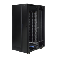
Removing/Replacing an Expansion Module
An expansion module increases the number of drives and data cartridge storage
slots available within your library.
To make repairs to an expansion module, perform one of the following procedures.
v “Removing an Expansion Module from a Library”
v “Replacing an Expansion Module in a Standalone or Rack-mounted Library (14U
or larger)”
To install a replacement expansion module, perform the following procedure.
v “Installing a Replacement Expansion Module Enclosure” on page 8-20
Removing an Expansion Module from a Library
1. Remove the following components from the expansion module for weight
reduction:
a. All power supplies (see “Power Supply (Primary and Redundant)” on
page 8-52)
b. All drive sleds (see “Drive Sled” on page 8-43)
Note: If not already done, have the customer remove all tape cartridges from
the module being removed.
2. Loosen the thumb screws securing the expansion module to the rear flange on
each Rack Kit rail, or to the module below.
3. Open the I/O Station door then the Access door on the expansion module.
4. From the front of the expansion module, remove the rack ears (see “Removing
the Rack Ears” on page 8-20).
5. Raise the gear racks (Refer to Figure 8-12 on page 8-15).
6. Raise the locating pin. (Refer to Figure 8-8 on page 8-11).
7. Loosen the thumb screw in the front.
8. Disconnect the module to module cables.
9. With a person on each side of the expansion module and a person in front of
the expansion module, pull the module out of the rack.
10. Place the module on a sturdy work surface.
Replacing an Expansion Module in a Standalone or
Rack-mounted Library (14U or larger)
1. If your library is to be reinstalled into a rack, perform the following:
a. With a person on each side of the expansion module and one person in
front of the expansion module, pick the module up from the work surface
and slide it onto the Rack Kit rails installed in your rack.
b. Lower the locating pin. (Refer to Figure 8-8 on page 8-11).
c. Tighten the front thumb screws.
d. Lower the gear racks. (Refer to Figure 8-12 on page 8-15).
Important: If the Expansion Module is at the bottom of the library, the gear
racks should remain locked in the UP position. Skip step d. if
the Expansion Module is at the bottom of the library. If the
Expansion Module is not at the bottom of the library, perform
step d.
Chapter 8. Add, Check, Adjust, Remove, and Replace Procedures 8-19
|
|
|
|
|

 Loading...

