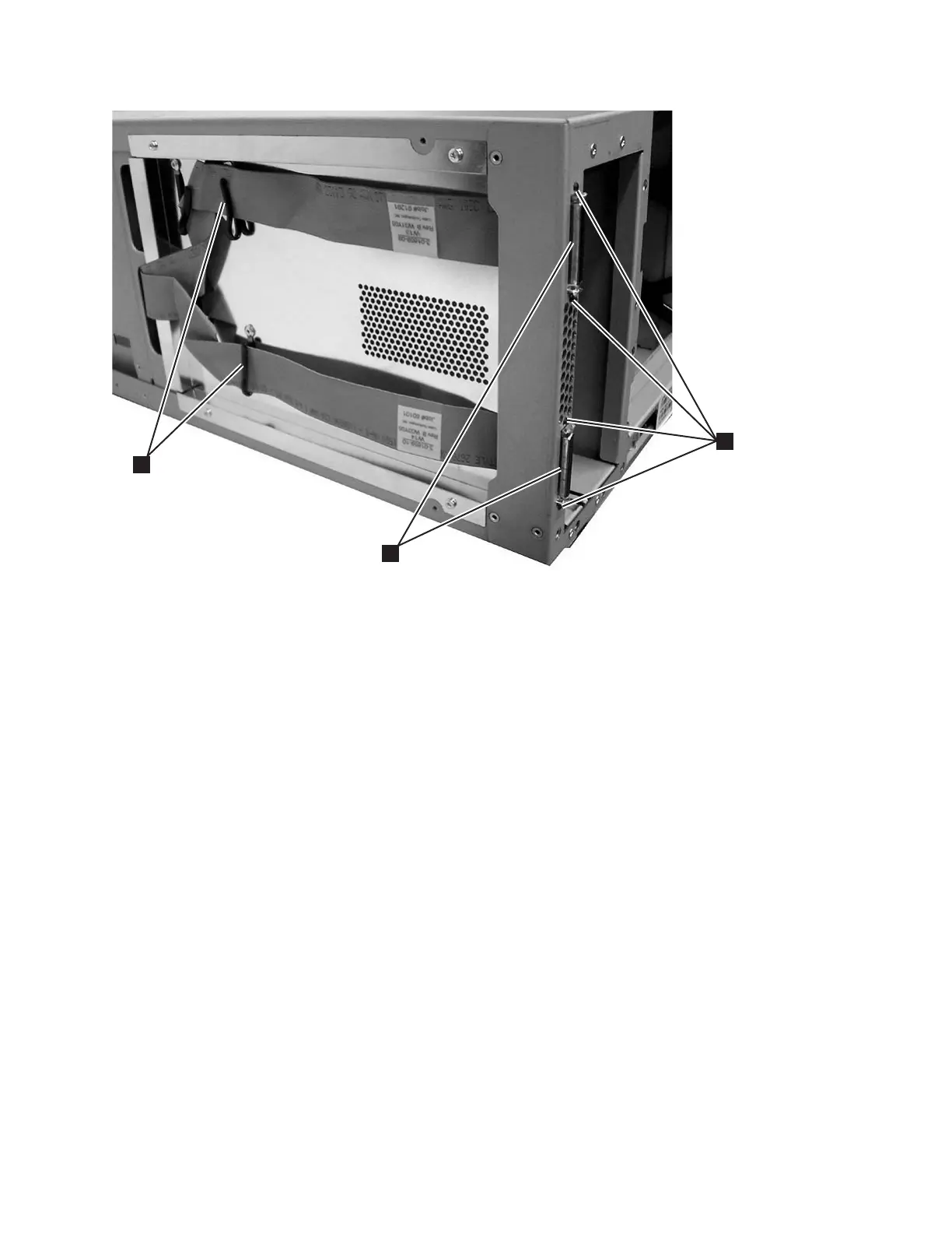
d. Remove the 4 T6 Torx screws (1 in Figure 8-130) holding the 2 D-shell
connectors (2 in Figure 8-130) on the back of the control module.
Carefully remove the 2 flat cables (3 in Figure 8-130) and D-shell
connectors from under the cable retainers on the side of the enclosure.
e. Carefully remove the BCB and cable assembly from the enclosure.
Replacing Internal Cables and Boards
To install the new cables and boards, perform the remove procedure(s) in the
reverse order.
Tip: When installing the new BCB it is easier to start the board mounting screws
(1 and 5 in Figure 8-124 on page 8-113) if you first stand the control
module enclosure on end.
Remove and Replace Drive Power Fuse
Each library module has an external drive power overload fuse that serves as a
protective device for all drive sleds installed in that module. The control module
has a 4 amp fuse and a 9U expansion module has a 7 amp fuse. The external drive
power overload fuse will blow if excessive current is being drawn by the drive
sleds.
Removing a Drive Power Fuse
1. Perform “Preparing a Library or Library Module for Repairs” on page 8-4.
2. Remove all power supplies in the library module with the blown drive power
overload fuse (see “Removing a Primary Power Supply” on page 8-53).
1
3
2
a66mi099
Figure 8-130. D-shell connectors and flat cables, side cover removed
Chapter 8. Add, Check, Adjust, Remove, and Replace Procedures 8-119