Removing the Operator Panel
1. Perform “Preparing a Library or Library Module for Repairs” on page 8-4.
2. Open the I/O Station door.
3. Open the Access Door. The Operator Panel is located on the backside of this
door.
a. Remove the black protective cover from the back of the Operator Panel.
b. Use a flat blade screwdriver to pry up on the plastic retaining pin (1 in
Figure 8-26 on page 8-29).
c. Squeeze the black plastic cover on both sides to remove it from the Access
Door.
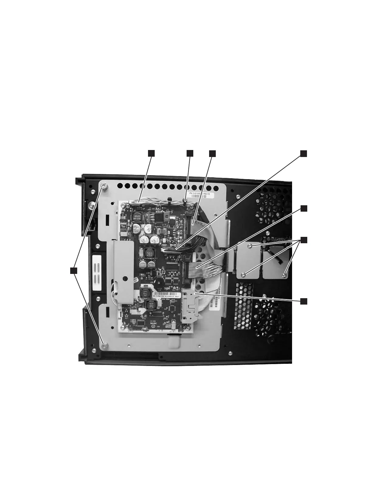
4. Disconnect the four cable connectors that are attached to the Operator Panel
(see 1, 3, 5, and 7 in Figure 8-29).
5. Cut the cable tie (2 in Figure 8-29) if necessary.
6. Unscrew the two captivated screws (8 in Figure 8-29) located on the left side
of the Operator Panel.
Important: When removing the final screw, hold the Operator panel to ensure
it doesn't fall.
7. Swing the panel to the right then lift it from the Access Door.
a66mi088
2
3
4
1
5
6
8
7
Figure 8-29. Operator Panel cabling
Chapter 8. Add, Check, Adjust, Remove, and Replace Procedures 8-31