9. Open the I/O Station door then the Access Door of the control module to
expose the control module alignment pin (1 in Figure 8-8 on page 8-11) and
front thumb screws (2 in Figure 8-8 on page 8-11) behind the Access Door
and behind the I/O Station door
10. Loosen the front thumb screws.
11. Lift and rotate the control module alignment pin to lock the pin in an up
position.
12. With a person standing on each side of the control module, pull it out of the
rack.
13. Place the control module on a sturdy work surface
Replacing a Control Module in a Standalone or Rack-mounted
Library (14U or larger)
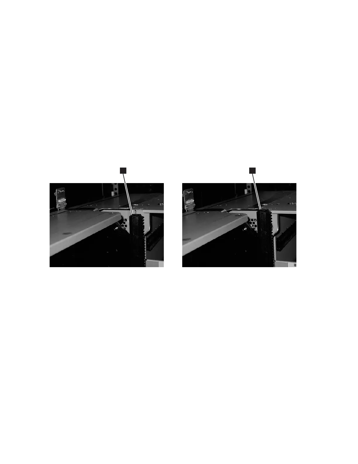
1. Ensure that the front and rear gear racks are in the upper position (see 2 in
Figure 8-9).
2. Ensure that the module-to-module alignment pin (1 in Figure 8-8 on page
8-11) is in the raised position. If necessary, raise the pin and rotate it half a
turn to lock it in the raised position.
3. With a person on each side of the control module, pick the control module up
from the work surface and slide it partway onto the expansion module in the
rack using the guide slots on the top of the expansion module and the bottom
of the control module.
1 2
a66mi095
Figure 8-9. Gear racks (down and up)
8-12 TS3310 Tape Library Maintenance Information